
Cylinder head (before and after) redesign using netfabb Selective Space Structures software and 3D-printed for lightweighting. The original solid part weighed 5.1 kg while the additive design weighs just 1.9 kg. The cooling effectiveness of the cylinder head internal volume is greatly increased, too, since the “honeycomb” structure increased the functional internal surface area from 823 cm3 to 10,223 cm3. Image courtesy netfabb.


Latest News
January 1, 2015
In the world of astronomy, 2015 is the International Year of Light, a year dedicated to education about generating, controlling and detecting photons. In the world of engineering, it appears 2015 will be the International Year of Lightweighting, with efforts dedicated to generating, evaluating and identifying the lightest and best mechanical designs—fast. Like the view you get with a powerful telescope, the insight you gain from lightweighting software is exciting stuff.
For traditional automotive and aerospace applications, the goal of lightweighting is to reduce energy consumption, but in many other industries, the benefits can go even further. Lighter designs save on raw material quantities and/or use alternative materials, come in at a reasonable cost, maintain or increase the desired strength and may improve such behavior as internal cooling.
The concept and goal of lightweighting is good in so many ways that dozens of software products now incorporate it in the design workflow. Desktop Engineering spoke to three such companies whose software products (different yet complementary) are representative of the many resources now available in this field: solidThinking, netfabb and Autodesk.
Design Guidance, Pre-CAD
It makes sense that the better the initial concept design, the easier it is for the mechanical engineer to make that design practical and manufacturable; also, the easier it is for an analyst (who may also be the engineer) to fine-tune that model for the best possible operation.
What if there was a way, even before you drafted a CAD model, to zero in on the best general shape, size and structure of a part? What if you could have the confidence that this part had already been optimized such that the minimum amount of material had been used to support specified, real-world loads? Only then would you invest time in generating detailed CAD geometry with exact dimensions and the requisite manufacturing necessities of fillets and chamfered edges. That’s the premise behind Inspire, the concept design package dedicated to lightweighting from solidThinking, an Altair company.
“We position Inspire as a concept design tool, not a detailed CAD tool,” says Jason Napolitano, solidThinking executive vice president of Global Sales. “You use it for the very first designs. Once you have the load patterns defined, you bring that model into the CAD program and validate it with FEA (finite element analysis).” Inspire fits into the workflow at the beginning, supporting a process to investigate structural concepts that either maximize stiffness or minimize mass.
Built on Siemens PLM Software’s Parasolid 3D modeling kernel and the Altair OptiStruct optimization engine, Inspire continually works to remove unnecessary material through the progression of one design concept to the next. “OptiStruct has been a great technology for 20 years,” says Napolitano, “but it was reserved for high-end CAE use. We saw a need in the design community and created an interface that was meaningful.”
Now in its fourth major release, Inspire 2014 takes users through importing an existing CAD file or defining a maximum blank “package space.” Jaideep Bangal, solidThinking senior application engineer, explains this with an example: “Imagine designing the mounting bracket for an automotive engine in the cramped space under a hood. The designer knows how much space he or she has; that becomes the starting point—the design space.” You can’t use more than that volume, but you can find ways to use less.
Inspire removes any features (e.g., fillets and small holes) that have little effect on the part behavior and guides the users’ placement of loads on surfaces such as on an axis or unsupported edge. Users then specify a variety of constraints: e.g., a pin can rotate but can’t slide in or out, an area of a part is clamped, or the load pattern cannot trigger a modal frequency. New features include constraining a part so that it can only move or deflect by a certain distance, the ability to create concentrated mass parts and an option to do some quick FEA.
Changing the values of a given load case and rerunning Inspire automatically updates the material geometry. Many visualization options let users see which regions of a part are in tension or compression, where areas of high stress are located, and how much the part deflects. Once the optimal (and sometimes organic) shape is established, invoking the “fit” function overlays smooth geometric boundaries, creating a file that can be saved and exported to any CAD system.
Inspire 2014 gives you an answer independent of manufacturing processes, though you can define shape controls that produce a design appropriate for stamping, forging or even additive manufacturing. Planned capabilities include generating cost comparisons of material use versus each design. As with its previous versions, the software runs on both PCs and Macs. (Editor’s note: For an example of how one manufacturer uses Inspire, see In Search of the Perfect Snowmobile Design.)
What’s Inside Really Matters
With the increased emphasis on minimizing part weight, it seems logical that another approach is to restructure a normally solid part as a shell with a honeycomb-like interior. This can produce an extraordinary material reduction that translates directly into weight savings, but the process requires two distinct steps: efficiently generating the internal design geometry and building the part with a 3D printer. Given today’s broad marketplace of 3D printers, the latter task can be accomplished by one of perhaps a hundred hardware systems (depending on required accuracy, material, durability, etc.) However, the former task—designing the airy structure—requires software such as netfabb’s Selective Space Structures (3S) package.
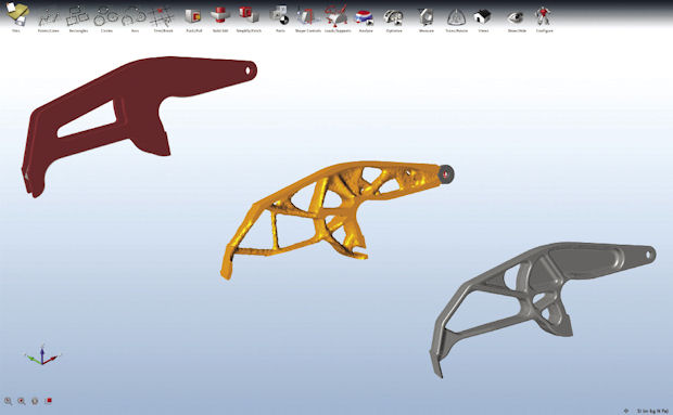 Workflow for pile driver bracket redesigned with solidThinking Inspire software for reduced weight. Image courtesy solidThinking.
Tailoring the properties of parts for optimal performance opens a world of possibilities because 3D printing enables new ways to use existing materials. Spinal implants, innovative furniture, automotive parts and structural aircraft components can be made strong and light, saving on total mass and sometimes adding a function like improved air-cooling or flexibility.
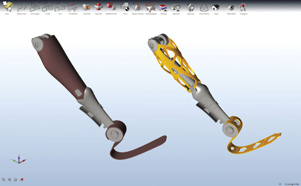 Prosthetic leg redesigned with solidThinking Inspire software for reduced weight. (Image courtesy solidThinking).
netfabb’s tag-line for 3S reads “from solids to structures in seconds.” To generate a volume structure, 3S breaks down the solid into box-shaped fragments or voxels, where the smallest voxel is a unit cell. These are usually built from a combination of nodes, bars and faces, producing shapes that look something like 3D versions of the letters Z, M, O and X, or snowflakes, soccer balls and stylized children’s game jacks. You also have the option to import an STL file and use that to establish a unit cell, and each bar can be designated as hollow to save even more on weight.
“The process is fairly automated,” says Ulf Lindhe, netfabb business development manager. “We have two types of structures: volume structures where you fill a volume with structures and surface structures where you wrap one layer of cells onto a surface.” Voxels can be edited and divided into groups, and each group can comprise different styles of unit cells for different regions of a single structure. Sizes and proportions are all user-defined.
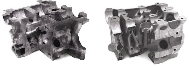 Cylinder head (before and after) redesign using netfabb Selective Space Structures software and 3D-printed for lightweighting. The original solid part weighed 5.1 kg while the additive design weighs just 1.9 kg. The cooling effectiveness of the cylinder head internal volume is greatly increased, too, since the “honeycomb” structure increased the functional internal surface area from 823 cm3 to 10,223 cm3. Image courtesy netfabb.
The level of detail possible within the confines of a part is amazing. A 3D printed part with a netfabb 3S internal structure may contain millions of unit cells. It has essentially been built with a new material. As such, Lindhe recommends that customers verify each structure type with testing and calculations; no FEA is done in 3S. Due to the typical size of a complex 3S-enhanced part, netfabb recommends outputting to a slice file for direct 3D printing.
After lightweighting an engine block with 3S, netfabb’s parent company, FIT Production, found the functional (cooling) surface had increased from 823 cm3 to 10,223 cm3, while the weight went from 5.1 kg to just 1.9 kg, a decrease of 62%. (Editor’s note: For more examples of lightweighting via 3D printing, see 3D Printing Takes Off and 3D Printing Advances Design.)
Fast Design-Space Model Validation
It’s clearly not enough to just create variations on a concept design and eyeball the pros and cons of each change. Vikram Vedantham, Autodesk business line manager for manufacturing industry strategy and marketing, says what’s needed are ways to validate concept models without analyst support. Autodesk already offers high-level feedback tools to designers concerned with airflow effects (via Autodesk FlowDesign) and with plastic-part manufacturability (via Autodesk Simulation DFM). Now, Autodesk Simulation Mechanical 2014 is bringing the insight of linear static stress analysis to the first-cut-design level through the addition of Parametric Design Studies.
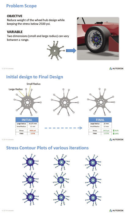 Design optimization workflow done with the Parametric Design Study tool in Autodesk Simulation Mechanical software. The goal was to reduce the weight of an automotive wheel hub while also reducing stress. Users quickly see the results of various changes in the geometric parameters. Images courtesy Autodesk.
“If you look at Simulation Mechanical today and the way that it interacts with Autodesk Inventor,” says Vedantham, “we’re getting closer and closer to seamless integration. If a user wants to optimize their design, they know what variables and constraints they want to work with. They have the ability to now pull the parametric geometry (the dimensions), specify which ones they want to alter, and work their way toward a more optimized design. Simulation Mechanical works in conjunction with Inventor whether you’re making changes based on stresses or displacements or changes in material.”
Ease of use is critical within Simulation Mechanical. Derrek Cooper, Autodesk director of product management, Digital Simulation, notes that two releases ago, the company introduced the Parametric Design Study editor to make the process appealing to design engineers rather than analysts. “Optimization is not new, and it can be topological, material-based or process-based,” Cooper says. “The challenge is: How do we make this more accessible and more mainstream?”
The ease of the Autodesk design optimization workflow starts with users bringing a model, whether a single part or an assembly, from Inventor into Simulation Mechanical. As with any FEA job, users first mesh the geometry then assign loads and boundary conditions and run the simulation.
Once the first analysis has been performed, clicking on the Design Studies button opens a window showing all the parameters in the model, including dimensions and material types and their current values. Users can select one, two or more parameters to be evaluated, designating a “design space.” Via the ribbon at the bottom of the window, they set upper and lower limits for the highlighted parameter values as well as the number of values to step through in each range then run an automated, methodical evaluation of each data set.
For example, on a part containing curved sections of two different radii, users could choose to vary one radius over a small range at three different values, while defining a larger range for the second radius covering four different values. Twelve possible scenarios would then be analyzed. Users can filter the results to see just the geometries that generate certain conditions, e.g., stress values of 20 psi or less. If activated, a built-in comparison table highlights the best design based on combined user criteria for weight, stress and deformation reduction.
Because material choice can also be evaluated as a Parametric Design Study variable, users interested in an environmental footprint can tap the knowledge base found in the Autodesk Inventor Eco Materials Advisor. The basic Advisor version includes a sample database and eco analysis capabilities; the full version, available for purchase from the Advisor’s developer, Granta Design, adds a database of 3,000 materials, more in-depth analysis and support for larger assemblies.
Users can bring the improved CAD design back into Inventor and send all data to an Excel spreadsheet or other program for further review. A good Parametric Design Study example is found on Autodesk Simulation TV, at http://goo.gl/B7AqaU. (Editor’s note: For another take on democratizing simulation, see this month's commentary from COMSOL CEO Svante Littmarck.)
More Tools Coming
The next stages of design and analysis software will support many more automated tools that conduct Design of Experiments (DOE) and include evaluation of organic shapes and even more diversity of materials. Within the automotive industry alone, the need to meet fuel efficiency requirements slated for 2025 is pushing for grand improvements. “Lightweighting is a key element of optimization,” says Autodesk’s Vedantham, “and it’s going to grow exponentially in the next three years.”
For More Info
Subscribe to our FREE magazine, FREE email newsletters or both!
Latest News
About the Author
Pamela Waterman worked as Digital Engineering’s contributing editor for two decades. Contact her via .(JavaScript must be enabled to view this email address).
Follow DE

