

March 1, 2006
By Mike Hudspeth
Design and manufacturing is tough work. You have to get it right the first time because there may not be a second. Competitors abound, trying to take your business for themselves. So what do you do? How do you survive? Well, for one thing you try to streamline as much as possible. Efficiency becomes a sort of mantra. You look for better ways to do what you do.
For these reasons, most designers have abandoned the drafting board for CAD. But what could be better than that? 3D. If you are ready to transition from 2D to 3D, Solid Edge 18 from UGS will help get you there.
|
|
| Solid Edge 18 |
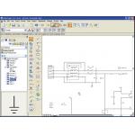
›› Figure 1: To create a schematic, all you have to do is find what you want on the menu to the left and drag it into the graphics area, placing it where you want it. You can connect it to wherever it should go.
Solid Edge 18 is a core component of what UGS calls its Velocity series—a modular family of fully integrated products designed to make passing information easy and safe between the component programs. Along with powerful 3D solid modeling, Solid Edge 18 includes Teamcenter Express (a subset of UGS’ Teamcenter PDM software), Femap Express (an FEA program), a new wire-harness design package, and Solid Edge diagramming. In short, it has almost everything you might want to make your job easier.
A History in 2D
Solid Edge has always made a big deal out of moving from 2D to 3D. Sure, they aren’t the only ones that can use a 2D drawing file to build a 3D part, but such out-of-the-box capability can cost a pretty penny from other vendors. Unless there is a very compelling reason to stay in 2D, engineers designing 3D parts and assemblies in 2D (you know who you are) should be considering 3D for it all.
|
|
| Solid Edge 18 |
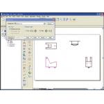
‹‹ Figure 2: Once you select what geometry you want for the front view, you merely tell Solid Edge V18 that it’s the front view. Solid Edge V18 will know that whatever is there is going to be the front of the model.
I once worked with a company that produced gauze pads and bandages, and 2D CAD was perfect for them. But they acquired some product lines from another company that had already gone 3D, so it was a major transition. They didn’t understand why anyone would want to put the effort into modeling instead of merely drafting. They had to be shown the speed and accuracy of modeling; how you don’t have to draw every view on the drawing and never have to worry about your elevations being complete. They went for it, and today are reaping the benefits.
You might know about solid modeling and FEA already, but UGS has something you may not have seen. Solid Edge 18’s new schematic environment can open or create schematics and extract information you need in your design. You can bring in pre-made blocks of entities to build your schematic from a library you can add to. You can bring in an image of a ground symbol and attach it to the schematic and version 18 will keep track of it for you. There’s a tree at the side of the screen, much like a feature tree, that will help you locate and query any block in the design (see Figure 1, above).
2D to 3D in a Snap
Solid Edge 18 has a 2D drafting capability that enables you to import 2D drawings from another CAD program or create your own. Interestingly, whether you are using a 2D drawing or a 3D model you can detail it in the same way. You always work in 1:1 scale and bring a view onto the drawing. AutoCAD calls it a Viewport. You can set the global scale of the drawing to whatever you want or set each view to be a different scale. It’s up to you. You can even set up relationships between entities that can be maintained when changes are made. It’s a whole lot like sketching. Just select the relationship you want and then the entities you want to share that relationship. They will snap right to it and stay that way until you indicate otherwise.
|
|
| Solid Edge 18 |
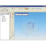
›› Figure 3: Solid Edge V18 puts the views you select into 3D space and aligns them to let you see what you have to work with.
We all have legacy data. If we’re lucky it’s CAD data. But what do you do with it if you want a 3D design? It would take forever to rebuild all your parts, right? Solid Edge 18 has tools for using that CAD data to generate 3D model data. One way is to import the 2D data and configure it according to your preferences. You can stop right there if you don’t really want anything more. You can maintain 2D legacy files from other CAD programs within Solid Edge 18, so you do not have to maintain old seats of old software. Just import your data into Solid Edge and edit it there.
|
|
| Solid Edge 18 |
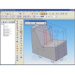
‹‹ Figure 4: You don’t have to fully enclose your geometry to sweep it. Just select enough to tell Solid Edge V18 what you intend and it will take it from there.
But if you want to convert a 2D drawing to a 3D model, you import your data and set up what geometry represents the different views of the model (see Figure 2, above). Once you’ve selected the three main views that describe your model, you can tell Solid Edge 18 that you want to create 3D geometry. It will take each view and put it on the appropriate plane and align them to create a box in 3D space (see Figure 3, above). The top view will go on the top plane, the front on the front, and so on. Select geometry from any of the planes to sweep into cuts or protrusions, even constraining them by selecting other geometry in another plane (see Figure 4, above). Once you start sweeping geometry, the 3D model comes together quickly (see Figure 5, below).
|
|
| Solid Edge 18 |
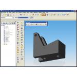
›› Figure 5: In no time at all you can take 2D legacy CAD data and turn it into 3D models. In this way you can re-use your old data and save the investment you’ve made over the years.
Solid Edge 18 can help you on your road to success. It has just about all the tools you’ll need to get there. And when it’s time to grow, you can easily upgrade to UGS’ NX product line. If you’re in the market for efficiency, though, this new version might just be what you seek.
Mike Hudspeth is a senior designer for a global medical company and has been using a wide range of CAD products for 20 years. He, his wife, two daughters, and their cats live outside of St. Louis, MO. You can send him an e-mail about this article by clicking here. Please reference “Solid Edge 18, March 2006” in your message.
A Few Words on Integrated Software
Integrated software can be a great thing. At the very least it allows you to pass data back and forth between applications with very little worry about compatibility. Most integrated packages even use the same interface across the board so using it can be a very familiar experience. The down side is that you are frequently limited by what your software vendor has to offer. If you want anything else, you lose any advantage you gain by buying integrated software in the first place. Analysis is a good example. If you are used to one package and your vendor uses another, you’ll probably end up buying additional software. The up side is that you get a lot of bang for your buck. If you aren’t familiar with the software that comes integrated, you may find it a good deal. You may even get to try some things you wouldn’t have bought otherwise. Most of the time the integrated software is an “Express” or lite version of some standalone package. If, after trying it, you find you like it, you can easily upgrade to the full version.—MH
Product Information
Solid Edge V18
UGS
Plano, TX
Subscribe to our FREE magazine, FREE email newsletters or both!


