A New Look at Subtractive Prototyping
When it comes to functional prototypes, subtractive manufacturing still offers some advantages not yet available in 3D printing.


September 1, 2013
| Related Coverage A New Look at Subtractive Prototyping, Part 2 Point-Counterpoint: Additive Vs. Subtractive Rapid Prototyping |
The allure of 3D printing is pretty difficult to resist. Once commercial 3D printers became available in the mid-1980s, the technology captured the imagination of many product designers. The affordable, consumer-friendly desktop printers brought the technology to a broader audience. It even popularized the term additive manufacturing (AM), as a way to distinguish itself from how machine tools traditionally remove materials to produce parts.
While traditional manufacturing, or subtractive manufacturing (SM), is still ideal for high-volume production of metallic parts, 3D printing offers the option to economically and speedily produce low-volume mockups with varying flexibility. It was an option previously beyond the reach of garage-dwelling tinkerers and independent inventors with limited budgets.
Nevertheless, in the shadow of 3D printing’s meteoric rise, SM continues to evolve. Today, with the availability of personal milling machines comparably priced to desktop 3D printers, subtractive hardware isn’t ceding its place in prototyping.
If the aim of your mockup is to study the design’s form, a 3D-printed part may be adequate. But when it comes to building mockups with the weight, strength and durability of manufactured parts, SM often proves to be a tough competitor, because milling is still a sensible way to produce metallic parts.
Then there’s the hybrid method: Some experts propose that a mix of affordable AM and SM technologies is the best approach to personal creativity and prototyping.
Market Comparison
According to AM industry watcher Wohlers Associates, “the market for 3D printing in 2012, consisting of all products and services worldwide, grew 28.6% (compounded annual growth rate, or CAGR) to $2.204 billion. This is up from $1.714 billion in 2011, when it grew 29.4%. Growth was 24.1% in 2010. The average annual growth (CAGR) of the industry over the past 25 years is an impressive 25.4%. The CAGR is 27.4% over the past three years (2010 “2012).”
Alan Levine, managing director of Open Mind Technologies, acknowledges that the advance of AM took away some market share from SM. “But subtractive techniques are also growing,” he adds. “We don’t see a declining market. Nobody is suffering here in subtractive.”
Open Mind specializes in CAM software, serving the numerically controlled (NC) manufacturing discipline. Analyst CIMdata tracks the NC market using reported end-user payments. “The worldwide NC software and related services market grew by 10% in calendar year 2011. The estimated end-user payments grew from $1.333 billion in 2010 to $1.469 billion in 2011,” CIMdata reports. The growth rate, however, dropped in 2012.
“In our most recent report, we estimated that the NC market grew 5.9% last year,” says Stan Przybylinski, CIMdata’s VP of research. Neither Wohlers Associates nor CIMdata track the subtractive hardware market separately; therefore, it’s difficult to compare the sales volumes of personal 3D printers (AM) vs. desktop milling machines (SM).
Cost Comparison
Personal 3D printers targeting the hobbyists, enthusiasts and DIY community start around $1,500. 3D Systems’ Cube and CubeX, for instance, are listed at $1,299 and $2,499 respectively. MakerBot Replicator 2, a desktop 3D printer, is priced $2,199.
Roland DGA’s iModela, described as “a digital hobby mill,” is priced $899. Roland’s portable milling machines and scanners, MDX-15 & MDX-20, are priced $3,495 and $4,995 respectively. Tormach’s benchtop PCNC milling machines—targeting machinists, engineers, inventors, makers and hobbyists—begin around $6,850.
The Purpose of Prototyping
Mcor offers hardware that prints 3D objects using standard office paper. Other companies are developing tissue-printing machines for biomedical applications. However, these technologies are not the norm: At the moment, the materials available for affordable in-house 3D printing are mostly limited to resin or plastic. If the purpose of your mockup is not just to study its geometric shape, but also to subject it to real-world testing, a 3D-printed part may not be sufficient—the prototype doesn’t accurately represent the metallic characteristics of the manufactured part.
 |
 |
 |
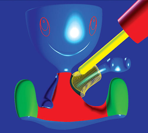
 Using Open Mind’s HyperMill software to simulate the milling sequence of an egg holder (A, B, C); the resulting prototypes were milled in the DMU 60 monoBLOCK milling machine (D). |
“Subtractive is particularly attractive when structural tests on actual materials are necessary, and you are testing fit and finish,” notes Rachel Hammer, product manager for Roland. “Also, high-quality surface finishes and prototyping on metals can only be achieved with subtractive technologies or very expensive high-end additive machines.”
Andy Grevstad, an applications engineer for Tormach, agrees: “When you talk about real-world materials—metals, composites, medical plastics, even engineering ceramics—subtractive is often still the only way to make those parts.”
For example, in medical device applications, a functional prototype is necessary to assess material strength, environmental reactivity or surface properties. When material properties are of primary importance to the design, the prototype must be made out of the same material as the final design, Grevstad points out.
Nishant Saini, the director of product sales and marketing at CAM software developer Geometric, uses a metal spring as an example. “If you have a prototype and you need to put it through 20,000 stress cycles,” he says, referring to a common practice to predict a product’s lifespan, “if you do it on a 3D-printed part, it may provide you with inaccurate results.”
Grevstad says that many people still only think of SM as a way to make machined parts, “but really, if you have a CNC machine, you can do so much more. For example: mill prototype circuit boards; build tooling for stamping, vacuum forming, or composite layup; make plastic injection molds or blow molds; and also create specialized jigs and test fixtures.”
The Role of CAM Software
Generally speaking, 3D printers can produce tangible parts from STL files, a format exportable from almost all professional 3D modeling software programs. With SM, the CAD model must go through CAM software to generate the machine code.
“CAM software plays an important role in how quickly and easily you can produce your prototype,” Hammer says. “Roland’s SRP Player CAM software, for example, uses a five-step wizard-based system so users can create parts with minimal training and without prior knowledge of NC code.”
Anthony Graves, Autodesk product manager for HSMWorks, concedes that CAM software is an added step in SM. His message to prospective SM technology consumers sitting on the fence: “Don’t be intimidated by CAM software, by the machines, by the moving parts. The software today is so easy to use. The tools you use inside your CAD program require a much steeper learning curve than those in CAM software.”
Graves joined Autodesk after the company acquired his previous employer, HSMWorks, a leading CAM software developer. In July, nearly eight months after the acquisition, Autodesk released HSMWorks Express for Autodesk Inventor, a free CAM plug-in for Autodesk Inventor CAD software users. The company plans to continue developing and supporting its pre-existing product HSMWorks Xpress for SolidWorks, despite fierce competition between Inventor and SolidWorks.
“The key is learning the machines,” says Graves. “Once you understand the concept of machining—2.5 axis, 3-axis, and so on—then you can easily find CAM software that’s easy to use.”
Observing the way a milling machine produces a part can give you insights into what’s possible and what’s not. For example, some geometric features are possible in 3- or 5-axis machines, but not possible in 2.5-axis machines. Other features may require a combination of 2.5- and 3-axis operations. Because of the way tool tips work around blocks of metal, square corners cannot be made; therefore, designs intended to be machined should include corners with acceptable radii.
“Not all designers have this ]NC manufacturing] background,” notes Geometric’s Saini. “Today, the process involves reviewing the design with the manufacturing team and going back and forth.”
Some CAD software can quickly scan the design’s geometry and identify potential manufacturing issues, such as geometric features that cannot be machined or molded. Autodesk Inventor users can use the Design Checker module (a free technology preview, currently available for download at Autodesk Labs) to scrutinize the geometry.
Similarly, SolidWorks CAD software users can accomplish this using the DFMXpress module, included with all versions of the software. “This tool enables manufacturers involved in mill/drill and turning CAM operations to assess their parts based on typical manufacturing rules,” explains Eric Leafquist, SolidWorks product portfolio manager, Dassault Systemes. The SolidWorks plug-in was developed by Geometric, a partner of SolidWorks. Geometric’s own DFMPro CAD plug-in addresses similar problems in milling, turning, drilling, injection molding, casting and sheet metal fabrication.
CAM software like HSMWorks, Open Mind’s HyperMill and Geometric’s CAMWorks let you simulate the machining sequence to produce your design using subtractive hardware. “]Our software] can look at complex parts, identify repeating characteristics, and build processes around these characteristics so they can be automatically programmed,” says Open Mind’s Levine.
Tall and Clean or Short and Curvy?
3D printers build geometry by depositing and bonding materials one layer at a time; therefore, the height of your design directly affects the build time. Simply put, the taller the design, the longer it takes to print. That is not the case with milling machines.
3D printers generally prove to be much more efficient in handling organic shapes—forms with complex spline curves. However, with 3D printing’s laying approach, extremely thin walls tend to collapse, because there’s no good way to build such features with sufficient structural strength using layers. Milling machines can produce thin-walled parts, but they, too, face similar challenges with structural integrity if the walls are too thin. In machining, deep pockets or inside corners with small radii could be difficult (and in some cases, impossible) for the end-mill to produce.
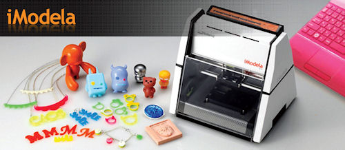 Roland DGA’s iModela, a hobbyist’s milling machine, is available for less than $1,000. |
“Using the same technology for prototyping allows you to simulate tool paths and other aspects of manufacturing,” says Roland’s Hammer. “As a result, you can virtually eliminate the costly reworks associated with designs that are not optimized for manufacturing.”
The Hybrid Approach
HSMWorks’ Graves says he believes the ideal setup is to combine 3D printing and desktop milling. “If users have access to both a 3D printer and an NC machine, then they can create parts for destructive testing ]better suited for parts produced with SM],” he adds. “Suddenly, they have eliminated the limitations in each, and it opens up a whole new world of capabilities and flexibilities.”
Even though AM and SM technologies appear to be the opposite of each other (especially in their namesakes), they are more complementary than you think. Like a good pair, one is stronger where the other is weak. Together, they form a combo that overcomes geometric complexity as well as material strength. If you have one without the other, the prototyping process is a compromise at best, a handicap at worst.
Kenneth Wong is Desktop Engineering’s resident blogger and senior editor. Email him at [email protected] or share your thoughts on this article at deskeng.com/facebook.
More Info
Subscribe to our FREE magazine, FREE email newsletters or both!
About the Author
Kenneth Wong is Digital Engineering’s resident blogger and senior editor. Email him at [email protected] or share your thoughts on this article at digitaleng.news/facebook.
Follow DE

