

Latest News
April 1, 2010
By Tim Webb
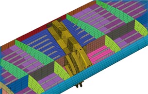 Figure 1: Model of load introduction rib (LIR) and surrounding flap and wing structure. |
In 2001, the Advisory Council for Aeronautics Research in Europe (ACARE) published a report that looked at air travel 20 years into the future. The report—European Aeronautics: A Vision for 2020—created guidelines for the continent’s 400,000 aviation workers to create an industry that satisfied “constantly rising demands for lower travel costs, better service quality, (and) the very highest safety and environmental standards.”
On the environmental front, the report set goals that would shrink the aeronautics industry’s footprint by cutting aircraft fuel consumption 50 percent, CO2 emissions 50 percent, and NOx emissions 80 percent by 2020. To reach these goals, aircraft engineers are competing to design lighter aircraft with greater range. One of the key strategies is replacing current metal components with innovative composite structures.
At EADS (European Aeronautic Defence and Space Company), a number of business units and partners are engaged in the development of “greener, cleaner” commercial aircraft. Through a global network of technical capabilities centers, collectively known as EADS Innovation Works, engineering teams at the $60.2 billion company are looking for ways to bring sustainability to aircraft design—one component at a time.
Sustainable Aircraft Design Takes Off
Dr. Tamas Havar, a specialist at an EADS Innovation Worksite near Munich, Germany, leads a variety of projects in the Structure Integration & Mechanical Systems department. He and his team are tasked with developing new aircraft structures using composite materials. “The goal of our ongoing analysis program,” Havar says, “is to reduce emissions and manufacturing costs by focusing on the development of innovative composite design and manufacturing methods.”
A project team of engineers from various EADS business units and university partners, lead by the Airbus High-Lift R&T group, recently completed the analysis of an advanced composite load introduction rib (LIR), an important wing flap support structure in the Airbus A340 aircraft. While an Airbus A340 component was used for this study, Havar says that the analysis results will be applied to new designs in general. In aeronautic applications, pre-impregnated carbon fiber reinforced polymer (CFRP) composites are typically the composite of choice. In this instance, however, the EADS engineering team—while looking to reduce costs—chose an autoclave-free manufacturing process that led to the use of textile composites instead. Textile composites are also used in the bulkhead of the A380—Airbus’ most composite-intensive aircraft to date.
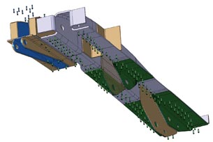 Figure 2: Modeling of rivets for load introduction rib (LIR). |
A critical factor in the design of composite aeronautic structures is how the parts attach to the surrounding aircraft structure. Current composite high-lift structures—such as a flap—typically use metal load introduction structures to attach to the wing. These structures, with fail-safe designs, lead to heavier aircraft and higher manufacturing costs. There are also differences in thermal coefficients between the connected metal and composite parts. Composite-load introduction structures, on the other hand, permit a damage-tolerance design, since a failure of one ply is compensated by other plies that remain intact. The use of composite material also eliminates the problem of thermally induced loads, since both the high-lift and load introduction structures are made of the same composite materials.
The EADS Innovation Works team chose Abaqus FEA from SIMULIA to analyze the design of their composite LIR. “Abaqus is our preferred nonlinear solver,” says Havar. “It has powerful composite analysis capabilities, especially for 3D elements such as in our LIR study.”
Abaqus FEA Fuels Composite Analysis
Abaqus FEA is used throughout the product design lifecycle at EADS—to narrow down initial concepts, to design the preferred concept pre-design, and to ensure all specifications are met in the final design stage.
The new composite LIR included a drive rib with integrated lugs so it could be attached to the flap drive, and rivets to attach the assembly to the flap skin. The team’s goal was to trim manufacturing costs by simplifying the LIR’s geometrically complex pre-form so that its thickness was uniform, except in those areas where pre-forming could be relatively simple and inexpensive. The team’s solution used LIR profiles that allowed the pre-form layup to be automated, thereby minimizing manufacturing costs.
To model the new design, the EADS team—working within the framework of the German-funded Aerospace Program and Project HIGHER-TE (High Lift Enhanced Research: Trailing Edge)—needed to consider the complexity of the composite structures: thicknesses vary from 4mm to 10mm; plies run out and are chamfered with resin pockets; gusset fillers are used in the radius.
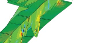 Figure 3: FEA results showing stress in composite fiber direction. |
“Given the variables inherent in composites, we needed to use 3D elements for the calculation of composite load introduction and to obtain an accurate analysis of all stress components,” says Havar. “Since delamination is a common type of failure for composite load introduction, both the transversal shear and peel stresses are of high interest.” With these factors in mind, EADS engineering group built the LIR model using a variety of different Abaqus elements. For the flap, the group used approximately 20,000 2D elements. For the LIR itself—and to calculate load introduction—it used approximately 100,000 continuum shell 3D elements, including hex-elements for the composite plies (with 4-8 plies per element, orthotropic properties per ply, and 3D element orientation) and penta-elements for the ply run out. Isotropic properties were applied to the resin matrix. All together the LIR model had approximately 450,000 degrees of freedom (see Figure 1).
The engineering team also had to demonstrate that each of the 324 rivets in the assembly, which attach the LIR to the surrounding structure, would withstand loading (see Figure 2). “This is dependent not only on the attached structures but also on the rivet material and the size of the rivet itself,” Havar says. To accomplish this, each rivet was modeled with an elastic connector between the parts. On one side the rivet was attached to the composite flap skin, and on the other side it was attached using a multipoint constraint to distribute the loads over the skin thickness. The resulting connector forces are used to calculate the reserve factor for skin-bearing failure and rivet fractures.
The engineers also examined the composite lugs used to attach the flap kinematic system to the LIR. The lugs were analyzed by applying loads using a rigid body element in the direction of the load. For each load case, the team created a new rigid body element due to the varying load conditions. To complete the LIR analysis, the EADS team calculated several load cases using the Abaqus implicit solver and postprocessing. In these scenarios, the flap was fixed at the edges with beam elements representing the test setup fixed at the ends in all three translational degrees of freedom. For some load cases, the beam elements at the outboard end were translated symmetrically causing an additional torsion on the flap. The analyses looked for both intralaminar (within plies) and interlaminar (between plies) failure, as well as rivet and lug loading. The analysis team used Fujitsu-Siemens Linux 64-bit workstations with run times of approximately 15 minutes for each load case.
Positive Results for Composites Analysis
If composites are key to the design of future sustainable “greener, cleaner” aircraft—with lighter weight, greater fuel efficiency, and fewer emissions—the results of EADS composite analyses were positive on all counts: in-plane and transversal stress components were within tolerances for the new composite LIR design (see Figure 3); strength specifications for all rivets connecting the LIR to the surrounding structure were met or surpassed; and performance of the composite lugs was within industry safety specifications.
“There’s no doubt that composite structures will increase in future aircraft,” Havar says. “To keep up with our ongoing innovation, we’ll need additional FEA capabilities.”
As design engineers and FEA software developers work together to solve such analysis challenges, composites will certainly be part of new, more environmentally friendly aircraft coming soon to a runway near you.
More Info:
Airbus
Tim Webb is the director of marketing communications and programs at Dassault Systèmes’ SIMULIA, based in Providence, RI. To comment on this article, send e-mail to [email protected].
Subscribe to our FREE magazine, FREE email newsletters or both!
Latest News
About the Author
DE’s editors contribute news and new product announcements to Digital Engineering.
Press releases may be sent to them via [email protected].


