
Solar Impulse 2 preparing for flight. Image courtesy of Solar Impulse.


Latest News
May 1, 2015
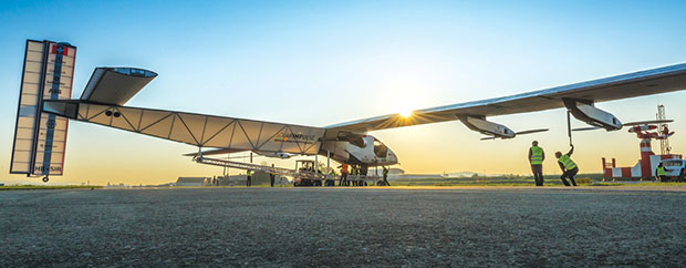 Solar Impulse 2 preparing for flight. Image courtesy of Solar Impulse.
The Swiss-based company Solar Impulse SA, led by aeronaut Bertrand Piccard and Swiss engineer André Borschberg, has set out to circumnavigate the globe in an airplane that runs on solar energy. They are flying the plane, in multiple stages, a total of 35,000 km (21,000 miles) for over 500 hours of flight. On March 9, Solar Impulse 2 took off on the first leg of its journey from Abu Dhabi, UAE, to Muscat, Oman. Borschberg landed after a 13 hour and 1 minute flight running on nothing but electricity generated from the sun. He flew Solar Impulse 2 to a maximum altitude of 6,383 m (20,941 ft), over a distance of 441 km, at an average speed of 33.88 km/h. Solar Impulse SA started with a prototype plane that first flew in 2009. In 2010, it flew for 26 hours in July — including nine hours at night. The design team was able to gather a lot of data from this prototype and applied what they learned to create Solar Impulse 2, the aircraft that would attempt to fly around the world. The task of designing an airplane that runs on solar power has myriad challenges. Minimizing the weight was the most crucial design challenge they faced. “The plane needs a lot of batteries, and batteries are heavy,” says Geri Piller, head of the structural analysis team at Solar Impulse. “It has to be really light.” Engineers had to optimize the plane’s design so that it was strong enough to carry the load of the batteries and still be as light as possible. The batteries make up nearly half the weight of the plane at about 2,007 lbs. They opted to use a composite sandwich structure made of a Kevlar paper honeycomb core. The design team for Solar Impulse used two main modeling tools for this project: CATIA from Dassault Systèmes for the 3D design and Femap with NX Nastran from Siemens PLM Software for analysis. Because CATIA was the primary design platform, the team felt that Femap was a natural choice as it easily accepts STEP and IGES files from CATIA. Once the 3D model was imported from CATIA, Femap could use that geometry as the basis for its finite element (FE) modeling. “Ply definition is really easy. We were able to jump into that topic very quickly using Femap,” he says. He also said that it was especially easy to simulate the composite materials in Femap, and they make up the majority of the plane. Once the 3D modeling and design work was finished, Piller and the engineering team ran simulations and analysis to fine-tune the design. They choose Femap because it fit their needs, they were familiar with it, and it could conduct the many different types of analyses (strength, buckling, large deformation and more) they needed to run on the digital model. CATIA was used to create the base 3D model, but once those files were imported, Femap modeling tools allowed the team to add 3D solid elements to the wings that represented Kevlar aramid paper honeycomb core. They did this to conduct analysis for local and global buckling effectively. Their FE models for the metal components ranged from 50,000 to 500,000 elements and the model of the wing contained 2 million elements. Their endurance analysis looked at 160 load cases. Femap has an API (application programming interface) that allowed engineers to create custom scripts. One script applied the company’s strength criteria to the composites in order to verify the laminate strengths. A second script helped evaluate the results. They were able to quickly identify where the laminate or sandwich structures failed, allowing for optimization of their design. The main challenge to designing the Solar Impulse 2 was the task of lightweighting the new plane. The plane needed to be bigger that the first iteration, and be able to carry a heavier load. To do this efficiently, Solar Impulse decided to use lighter materials. Solar Impulse, the prototype, used a material that weighed 100 grams per square meter. Solar Impulse 2 used a material that weighed only 25 grams per square meter on the wings. Weight-saving steps were also taken in designing the motor gondolas. The Solar Impulse 2 needs to fly farther and longer than the prototype, so it had to have larger, more powerful motors that weighed more. In order to compensate for this weight, the engineering team switched to a sandwich structure from a framework structure. They used Femap to optimize the components (facings and spar caps as examples) to ensure that the new gondolas could hold the additional weight. The Solar Impulse design is meant to demonstrate that sustainable power is possible. Solar Impulse 2 is using advanced material and construction techniques along with new battery technology to achieve its goals. Finite element analysis (FEA) made this design possible. Engineers were able to apply real world physics to their models without having to waste time and materials. At press time, Solar Impulse 2 is in China on leg six of 12 in its flight around the world, proving that solar-powered flight is indeed possible. More infoDesigning a Solar-powered Aircraft
The Tools for Flight
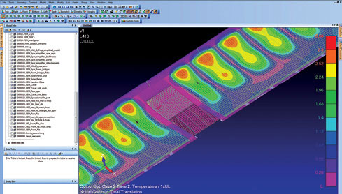 Simulation predicts structural deformation experienced as a result of temperature loading. Image courtesy of Solar Impulse.
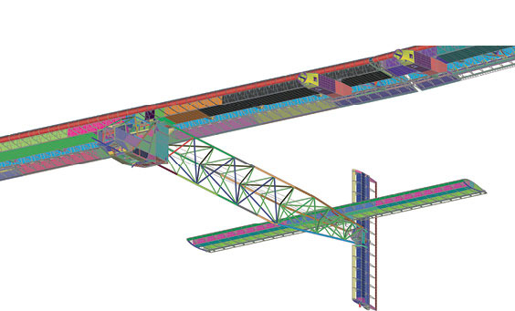 Simulation model of wing (with lower skin removed to show internal structural detail) used to verify strength and minimize weight of the structure. Image courtesy of Solar Impulse.
Lighter, Stronger, Faster, Bigger
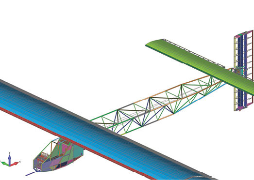 Complete simulation model showing close up of tail used to verify strength and minimize weight of the structure. Image courtesy of Solar Impulse.
Sustaining Innovation
Subscribe to our FREE magazine, FREE email newsletters or both!
Latest News
About the Author
Brian Benton is a freelance writer based in Florida. He writes the CAD-a-Blog website at cadablog.blogspot.com.
Follow DE

