Battery Modeling
Progress has been made in understanding next-generation battery energy sources, and the subsequent simulation technology that is now available to design engineers.


Latest News
July 2, 2012
By Steve Hartridge and Robert Spotnitz
Automakers have introduced many new hybrid and fully electric vehicles over the last couple of years. It’s now common for new vehicle announcements to have an obligatory “green” option—even for a high-performance Rolls Royce.
This need to offer fuel-efficient variants to potential purchasers has led to a massive increase in the so-called “electrification” of modern vehicles. This electrification normally takes the form of an electric motor/generator, power electronics and a battery energy source.
The recent trend for the inclusion of larger, more powerful batteries has provided an opportunity for lithium-ion chemistries to become the dominant energy source in such hybrid and electric vehicles. This is because lithium-ion batteries provide exceptionally high power and energy density. Lithium-ion batteries’ growing popularity has also benefited from the longer-term trend for the acceptance of modeling and simulation techniques in the design of complex components, particularly passenger vehicles. Established automakers already have a taste for a healthy mix of simulation and traditional testing when designing vehicles, so the need for such a mix when including lithium-ion batteries in a design is necessary.
This presents the simulation industry with the challenge to provide battery models.
Anatomy of a Battery
At the heart of any lithium-ion cell are the anode (or negative) and cathode (or positive) active materials and electrolyte. The active materials are particulates that are mixed with binder and conductive additives and coated onto metal foils that serve as current collectors. The anode active material is usually graphite or carbon, though lithium titanate is also used. The material is usually coated on a copper foil to distribute the current from the negative post along the electrode.
The cathode active materials most commonly used in automotive applications are lithium iron phosphate (LFP) or lithium nickel manganese cobalt oxide (NMC), although lithium nickel cobalt aluminum oxide (NCA) is used, as well as lithium manganese oxide (LMO) when blended with NMC or NCA. The material is usually coated on an aluminum foil.
Spurring on Tomorrow’s Discoveries Joint research projects, bringing together leaders in their respective fields, are the mechanism to move things forward. The U.S. Department of Energy is sponsoring a program of work to include lithium-ion cell modeling technology into industry-accepted CAE tools. CD-adapco is leading one such project, which includes Battery Design LLC, Johnson Controls Inc. and A123 Systems. It focuses on validating the methods discussed in this article. This project is overseen by the National Renewable Energy Laboratory, a Golden, CO-based authority in battery modeling. For more information, visit nrel.gov. |
Both the anode and cathode active materials are “insertion” or “host” compounds, which designates that they are structured in such a way as to provide vacancies that lithium can fill. The process of lithium insertion or de-insertion is gentle, and does not damage the structure. This means the process is reversible, enabling long cycle life.
The electrolyte is usually lithium hexafluorophosphate salt dissolved in a mixture of linear and cyclic carbonates. Unfortunately, the electrolyte is flammable, which is a major safety concern in lithium-ion batteries. The electrolyte fills the interstitial space between the particulates as well as the porosity of a separator. The separator prevents electronic contact between the positive and negative electrodes while allowing ionic communication.
This completes the components required to create a simple electrochemical cell, the heart of all lithium-ion batteries. The lithium-ion cell is called a “rocking chair battery” because during operation, the lithium simply “rocks” between the positive and negative electrodes. During discharge, lithium de-inserts from the negative active material into the electrolyte and transports to the positive active material, where it inserts. The reverse process takes place during charge.
The challenge for battery modeling is to predict how the cell voltage, current, temperature, shape and other factors vary during use, based on the design and composition of the cell.
Data History
One of the first noted publications proposing a physics-based, mathematical model of a porous insertion electrode was by Atlung, West, and Jacobsen1. This paper, published in 1979 in the Journal of the Electrochemical Society, presented a model that predicted the energy available depending on the current required. However, it took until 1994 for this model to be extended to predict the performance of a complete cell consisting of dual porous insertion electrodes.
This model of a lithium-ion cell containing dual porous insertion electrodes, the “DUAL” model, was authored by Fuller, Doyle, and Newman2—and remains a milestone in lithium-ion cell models. This model identified five dependent variables, resolved across the two electrodes, to predict how the cathode and anode will perform within the electrochemical system. As well as the overall performance of the cell, this model provided insight into limiting factors of a given cell design.
As an example, a battery engineer could now visualize how the performance of a cell under very high current charging could be limited by the rate at which the lithium ions could diffuse into the anode material. Previously, a cell would be tested to understand that at a high rate its performance started to degrade. However, knowing how to improve the cell would largely be based on rules of thumb. Now, using the DUAL model, it was possible to understand the limiting factor within the cell—and thus adjust appropriate quantities to maximize a design, within given limits.
Since the release of this milestone paper, there have been many extensions, variants and sophistications to this model, to keep up with technology developments.
Although the DUAL model represented a step change in battery cell modeling fidelity, it does contain limitations that have become more apparent as lithium-ion cells have grown in size and capacity. In a small coin cell—something you might find in a wristwatch—it is reasonable to assume the whole of the cathode and anode are operating in the same conditions, both electric and thermal. However, in a larger, automotive-sized lithium-ion battery cell, this assumption is no longer valid. Therefore, a DUAL model has to be used in conjunction with solvers that can account for these variations.
Capturing Variations
One of the first publications that attempted to capture these effects, albeit for lead-acid cells, was by LaFollette and Harb3. Here the electrochemistry model was adjusted to allow a number of such models to work within an orthogonal grid, thereby capturing the variations along the length or height of the cell. This is the next advance in battery cell modeling that has now been successfully applied to automotive-grade batteries, allowing simulation to resolve the internal gradients within a cell. Figure 1 shows the results of a simulation of a 26Ah pouch type cell compared to an infrared image, reported by Damblanc4. Temperature is plotted in both cases—and it can be seen that by using this approach, good agreement can be achieved.
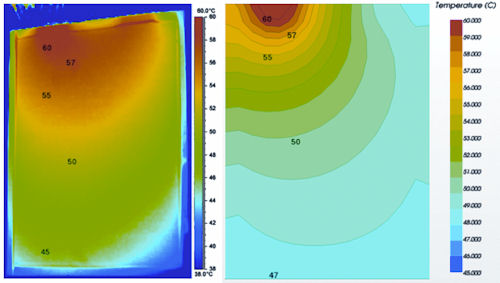 |
| Figure 1: Comparison of simulated results (right side), with previously reported IR temperature measurements4. |
This advance moved battery modeling to three dimensions, allowing internal gradients to become visualized across the length and breadth of the cell. This same development can be transformed into a spiral structure, allowing the modeling of spiral cells as well as stack-type cells. Both stack and spiral designs are popular in larger-sized batteries.
Moreover, once such simulation architecture is created, then the single cell model can be replicated to create module and pack models. By tightly coupling the solution of both the electrochemistry and thermal environment, accurate simulations can be achieved. Figure 2 shows one such simulation, whereby a series of cells are arranged to create a module. This particular module experiences three pulsed discharges, and shows the subsequent temperature profile and electrical response.
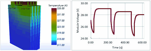 |
| Figure 2: Simulation results for an eight-cell module; temperature is shown on the left and overall module response is shown on the right. |
This electrochemical simulation structure is now integrated in the 3D computer-aided engineering code, STAR-CCM+ by CD-adapco, to provide commercial users with the ability to simulate the behavior of standalone cells, modules, packs and systems. A typical model would also include the cell-to-cell electrical connections, which can contribute heat to the system, as well as liquid or air cooling, which controls the cells’ temperature during operation.
What Lies Ahead
A new field of electrochemical modeling was initiated in 2005 by the work of Garcia et al.6, who proposed a new approach simulating lithium-ion cells. This work did not use the volume-averaging approach used in the DUAL model, but instead resolved the microstructure of the electrode as a set of spherical particles. This approach provides the lithium-ion cell designer with a more realistic understanding of the diffusion processes during operation, and changes in particle shape and surface.
Figure 3 shows a section slice through a model, solving for the electrical current and the lithium diffusion, showing the anode and cathode particles. The particles are colored by the amount of lithium that has been absorbed, and it is clear there is non-uniform utilization of the active materials. The option for microstructural modeling is also available in the STAR-CCM+ software from CD-adapco, providing a tool for enhancing electrode design.
 |
| Figure 3: Lithium ion concentrations in a resolved 3D electrode model. |
The most significant remaining challenge in the simulation of lithium-ion batteries is the prediction of the degradation, or “aging,” of a cell as it is used. Aging refers to all the processes that affect the capacity and impedance of the battery, which are broadly characterized by two categories: calendar aging and cycle aging.
Calendar aging refers to the degradation of the cell because of internal processes that take place when the cell is left without being used. Models have been presented that show good agreement across a range of cells, and the significant process is thought to be the loss of active lithium into the solid-electrolyte interface (SEI) layer, which covers the active materials. The growth of the SEI reduces the amount of lithium that can be cycled—and also increases the internal resistance of the cell during operation. Ploehn et al.7 published a general model for SEI growth, which is useful for simulation of calendar-aging effects.
Cycle aging remains a significant challenge for the simulation industry. Many projects are currently under way to quantify this effect. However, having an understanding of the internal thermal and electrochemical gradients will provide a framework to include breakthroughs when they happen.
For now, lithium-ion battery modeling remains a rapidly developing science. The future for simulation methods in this industry is bright, with tools available now that can provide engineering insight. There are also some significant challenges waiting for technical heroes to overcome—all in all, making this an exciting time for engineers in this area.
Steve Hartridge is director of electric and hybrid vehicles for CD-adapco. Robert Spotnitz is president, Battery Design LLC. Contact them via [email protected].
More Info
References
1 S. Atlung, K. West, T. Jacobsen, “Dynamic Aspects of Solid Solution Cathodes for Electrochemical Power Sources,” J. Electrochem. Soc., Vol. 126, No. 8 (1979) pp. 1,311-1,321.
2 T. Fuller, M. Doyle, J. Newman. “Simulation and Optimization of the Dual Lithium Ion Insertion Cell,” J. Electrochem. Soc., Vol. 141, No. 1 (1994) pp. 1-10.
3 R. LaFollete, J. Harb. “Mathematical Model of the Discharge Behaviour of a Spirally Wound Lead-acid Cell,” J. Electrochem. Soc., Vol. 146, No. 3 (1999) pp. 809-818.
4 G. Damblanc, S. Hartridge, R. Spotnitz, K. Imaichi. “Validation of a New Simulation Tool for the Analysis of Electrochemical and Thermal Performance of Lithium Ion Batteries,” JSAE Congress, May 2011.
5 U.S. Kim, C.B. Shin, C.-S. Kim. “Effect of Electrode Configuration on the Thermal Behavior of a Lithium-Polymer Battery,” J. Power Sources, 180 (2008) pp. 909-916.
6 R.E. Garcia, Y.-M. Chiang, W.C. Carter, P. Limthongkul, C.M. Bishop. “Microstructural Modeling and Design of Rechargeable Lithium-Ion Batteries,” J. Electrochem. Soc., Vol. 152, No. 1 (2005) pp. A255-A263.
7 H. Ploehn, P. Ramadass, R. White (2004). “Solvent Diffusion Model for Aging of Lithium-Ion Battery Cells,” J. Electrochem. Soc., Vol. 151, No. 3 (2004) pp. A456-A462.
8 “Thermal Management Studies and Modeling,” A. Pesaran, NREL, DOE Vehicle Technologies Merit Review, Maryland, February 2008.
Subscribe to our FREE magazine, FREE email newsletters or both!
Latest News
About the Author
DE’s editors contribute news and new product announcements to Digital Engineering.
Press releases may be sent to them via [email protected].


