

Latest News
August 1, 2013
Olivier Guillermin, Ph.D., director of product and market strategy at Siemens PLM Software, urged me to take a good look at the boats skipping along the San Francisco Bay in the America’s Cup. (I happen to live in the area.) Many of them are examples of how composites can be used to create lighter, faster vehicles with aeronautic advantage, he pointed out.
But if I need some insights into how composites behave, I might have to study how a tailor works. In fact, technical literature on composites borrows heavily from the dressmaker’s vocabulary: plies, patterns, draping, wrinkling, weaving and shrinkage. Simply put, composites are layers—sheets, if you will—created from two or more materials.
“The good thing about composites is, you can design your material. The bad thing about composites is, you have to design your material,” Guillermin quips. And that may be the key to working with composites: The way they react to stresses and loads is inseparable from the way the materials are put together.
Beginning at Ply Building
At the fiber level, the weaving method determines the stretching, shrinking and expansion behaviors of composites. They’re generally not isotropic: When reacting to forces and stresses, they don’t expand, contract and stiffen uniformly in all directions. The more sophisticated composite users take that into consideration, and use that to their advantage.
In December 2011, Siemens acquired Vistagy, bringing the latter’s composite-design software Fibersim into the Siemens software portfolio. The new software complements Siemens’ existing NX design software suite, particularly the NX CAE Laminate Composites module for building FEA models of composite models. In early 2013, Siemens also acquired LMS International, including the Samcef Finite Element Analysis (FEA) software suite with a large spectrum of linear and nonlinear composites analysis and optimization capabilities.
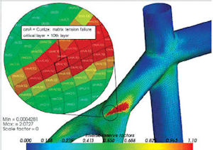 A close-up look at simulation results of a bike component covered with composite materials. |
Fibersim gives you insights into what happens during the manufacturing process. “For example, an automated fiber placement machine used to produce composite plies has a minimum course length,” says Guillermin. “It cannot lay down less than a certain inch of fiber length. So the engineer has to design ply shapes a certain way to accommodate that.” Such functions in Fibersim, Guillermin explains, “let you know whether you are designing manufacturable plies, or will have issues when producing them.”
Materialistic Behavior
If you’re using standard manufacturing materials—plastic or steel, for example—defining the material in simulation software could be as simple as picking the corresponding material from a library. But with composites, this option is not always available.
“We have composite materials in our software’s library. It’s in our database,” notes Pierre Thieffry, Ph.D., ANSYS Software’s lead product manager for Structural Mechanics. “However, everyone will use a different flavor of carbon or fabric, so they will have to characterize it on their own. That’s one of the challenges with composites, because there’s a huge variety.”
The material properties you need for simulation (how much it expands, how it behaves at high temperature, and so on) may be available from the supplier, but if the supplier is not willing to part with this proprietary data, you may need to conduct lab tests—or hire a lab to do the testing—to obtain the data.
“This is a general problem in the industry,” says Bob Yancey, Altair’s senior director for global aerospace. “First of all, the amount of data that needs to be captured is at least an order of magnitude more than with isotropic material systems. Secondly, many companies that use composites create their own material databases and keep this information proprietary.”
Last September, simulation software maker MSC acquired e-Xstream engineering, which specializes in material modeling.
“We have approximately 200 material models in our database from a number of material suppliers, as well as models we’ve created based on public data available from Campus,” says Bob Schmitz, business development engineer for e-Xstream engineering. “We also offer the ability to encrypt the material models, so that a supplier can provide the end user an accurate representation of their material’s performance without revealing the details of the material. For internal use within a company, we also provide control over who has access to upload or change material data. This is a level of quality control over material data management and an aspect that our parent company is implementing at a much larger scale with its new product, MaterialCenter.”
Layered Complexity
As Siemens’ Guillermin observes, “most composite parts are over-designed.” That’s because designers have to compensate for the uncertainties involved with composite behaviors because of a lack of data. “There’s currently still insufficient information about progressive damage, fatigue. There’s ongoing research in this area,” he adds.
The wear-and-tear prediction for composite is also made more difficult by the fact some of them behave like woven fabric, not metal.
“Because they’re fabric, you don’t always get consistent material properties,” says Guillermin. “They differ from roll to roll. There might be some waviness in one roll, but not in the other. And transportation might affect the rolls.” Not all composites are woven, Guillermin points out. In fact, aero structures use unitape or non-crimp fabric (NCF), which are stitched layers of unitape.
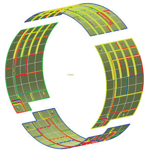 Laying out the composite plies on an airplane fuselage in Siemens PLM Software’s Fibersim. |
ANSYS’ Thieffry points to layers as the reason for composite simulation’s complexity. “With regular materials, you look for maximum stress, deformation, and so on,” he says. “With composites, you have many layers, so you have to look at the results layer by layer.”
Meshing
ANSYS’ Thieffry says that most composite simulation requires surfacing meshing to address the layers. But some structures that are made up entirely of composites (some turbine blades, for instance) require a different meshing. “In the way we do it, to get the final volume mesh, we start from the surface mesh,” he says, “then extrude it along a spline.” It’s a method that imitates how composites are built in the manufacturing process. Plies are manufactured by adding layers into a mold to build thickness along a profile.
The ANSYS Structural Mechanics suite includes Composite PrepPost. According to ANSYS, “Engineering layered composites involves complex definitions that include numerous layers, materials, thicknesses and orientations. The engineering challenge is to predict how well the finished product will perform under real-world working conditions. This involves considering stresses and deformations as well as a range of failure criteria.”
“With composite meshing, you need to decide how detailed you want to get,” says Guillermin. “If you’re going to take a smeared approach ]treat the stack of composite as a single homogeneous entity], then it’s simpler meshing. But if you want to study each layer separately, you need specialized pre- and post-processors that use structured mesh that mimic or follow the layers.”
Most of the time, the mesh does not detail each and every layer, Guillermin notes. It could be several layers at once, or a laminate per element thickness.
Altair’s Yancey explains that “for thin composite structures, we have developed shell elements to model the laminate structure, which is good for predicting the stresses and strains in the individual layers, but they are poor for modeling the stresses and strains between layers and at laminate boundaries. For solid composite structures if ]the material] is anisotropic, which is often the case, the meshing method doesn’t take this into account. To get the stresses and strains between layers and at laminate boundaries, solid element approaches are preferred, but this can lead to very long compute times. Advancements are needed to achieve detailed and complete results with computational efficiency.”
Optimizing
In typical optimization exercises, the designers look for the best topology or geometry to counteract the anticipated load, pressure or force. But in composite part optimization, the emphasis falls on thickness. In software like Vanderplaats Research & Development’s (VR&D) GENESIS, “You’re looking to determine the number of layers you need for your design,” notes Juan Pablo Leiva, the firm’s president. “We call it thickness optimization. But since you usually know how thick each layer is, you’re actually looking for the best number of plies.”
Yancey reports that Altair has several exclusive capabilities for composite design optimization within OptiStruct, where the company can optimize the thickness and shape of individual plies and the stacking sequence for the laminate.
“Most engineers can tell you where you need to have material,” Yancey says, “OptiStruct can help you understand where you don’t need material, which helps you design structurally efficient systems.”
Orientation
Because composites don’t expand uniformly in the same direction, understanding the expansion behavior and orienting each sheet or layer to account for the anticipated expansion is also a critical part of composite design.
“For each fabric, you need to know what the reference is,” says Thieffry, referring to the 0 mark in the virtual 3D space. “For each fabric, there’s reference direction per element ]mesh], because the direction changes depending on the curvature of the region it covers.”
That means millions of directional definitions for a sheet of composite subdivided into millions of elements. For practicality, the process of defining these directions has to be automatic, not manual.
VR&D’s Leiva says the composite fabric’s expansion behavior is influenced “not only by the way the fibers in the fabric are woven, but also by the way the user lays them out. Our software recognizes that composites are anisotropic, so if you place a load, the FEA will produce a deflection, and you’ll be able to see on the computer screen if there’s going to be any warping.”
Wrinkle Detection
In aerospace and automotive, speed advantage comes from subtle and complex geometry, designed specifically to reduce drag. Because composite layers hug these intricate curvatures, it’s important to be able to predict where wrinkling could occur and fix these regions before moving into production.
“The fabric follows the curvature of the design,” said Siemens’ Guillermin. “It’s very hard to predict what it’s going to look like, even for an expert. An aspect of simulating the manufacturing process in Fibersim is the ability to simulate draping—so you can see possible areas of wrinkling, bridging or micro-buckling before you go and make the part.”
“In fact, in some Formula 1 cars, engineers take advantage of that twisting and warping behavior,” says VR&D’s Leiva. This is different from the unintentional deformation resulting from the tug and pull on composite fabrics (those are the ones you want to avoid). By strategically introducing deflections, “you can make the car to get stiffer when going straight, and to deflect more when turning to help with aerodynamics,” Leiva explains.
Schmitz says that e-Xstream engineering’s focus in Digimat, the company’s nonlinear multi-scale material and structure modeling platform, is the modeling of the material performance. “In this case,” he says, “we will use the material orientations from the draping simulation to predict the material performance of the as-manufactured laminates.”
Some Composite Wisdom
Composite parts inherit the physical behaviors and chemical properties of constituent materials, so they can be produced to meet the desired flexibility, lightness, and strength—hence their appeal. The growing use of such materials is evident when you compare Boeing’s programs for the 777 and the 787 Dreamliner. The 777 uses 12% composites, 50% aluminum; the 787 uses 50% composites, 20% aluminum. (Editor’s Note: For more, read Beth Stackpole’s article “Design Tool Market Reshapes around Composites” on page 22.)
“Since composites are manufactured materials, you cannot decouple manufacturing from design,” Guillermin warns. “The way they’re laid up and joined, the manufacturing defects inherent to the parts—they affect the design. With metal, somehow you might be able to treat the metal properties separately from the geometry of your design. But with composites, you cannot do that.”
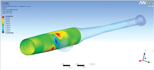 Simulation results of a baseball bat with composite materials, shown here in ANSYS software. |
Altair’s Yancey has found that over the last decade, modeling capabilities for composites have dramatically improved—“but there is still plenty of room for improvement. CAE modeling for isotropic materials has been developed over several decades. Real innovations will be required to achieve the modeling efficiency for composite structures that we now enjoy with isotropic material systems.”
VR&D’s Leiva says that while composite parts have become the norm in Formula 1 and other special vehicles, the relatively high cost of composites has prevented more widespread use in passenger vehicles. Through the use of optimization, designers can find the best places to put composite materials to get the best performance per dollar.
“Failure and progressive damage are two topics that are of high interest to our customers, and you will see more capabilities developed and refinement in these areas,” predicts e-Xstream’s Schmitz.
ANSYS’ Thieffry agrees: “You’ll be able to conduct detailed analysis, down to the fiber level. Maybe you’ll even be able to go to the specific fiber in a layer where it might fail.”
But is there any chance research might allow us to go even deeper? “We’re not going down to the electron level,” Thieffry concludes.
Kenneth Wong is Desktop Engineering’s resident blogger and senior editor. Email him at [email protected] or share your thoughts on this article at deskeng.com/facebook.
More Info
Subscribe to our FREE magazine, FREE email newsletters or both!
Latest News
About the Author
Kenneth Wong is Digital Engineering’s resident blogger and senior editor. Email him at [email protected] or share your thoughts on this article at digitaleng.news/facebook.
Follow DE

