Blimp-based Power Plant Modeled in SolidWorks
Designs that Will Change the World, Third Place: Aerostat Wind Turbines has a keen interest in problem solving and an entrepreneurial spirit to raise wind power to a new level.


Latest News
December 1, 2009
By Tom Kevan
Barstow, CA–based Aerostat Wind Turbines has taken existing technology and materials, as well as time-proven concepts, and created the Airborne Wind Turbine (AWT). The design promises to enhance energy production, reduce manufacturing costs, drastically reduce the time required to achieve a return on investment, and deliver inexpensive electricity, particularly to remote locations.
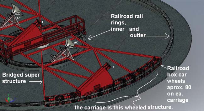 The base station of the Airborne Wind Turbines anchors the platform to the ground and accommodates changes in orientation with a structure made up of inner and outer rail rings and approximately 80 railroad car wheels. As the airborne blimp self orients to the direction of the wind, the base station tethers move along the rings. |
The Design Team
Aerostat’s design team is a unique collection of people, and the team’s unusual composition shakes up conventional thinking about innovation and design.
The concept for the AWT was the product of an “idea man,” but not a trained engineer. Lynn Potter, the inventor of the AWT, is by profession a prosthetist. His efforts were supported by Brad Merrell, an engineer with the civil engineering firm of Merrell Johnson; Jim Merrell, who helped with project management; and Christopher Gorham, who produced the system’s CAD drawings.
Aerostat’s team used SolidWorks to design the ATW’s base station and shrouded turbine modules. The software proved particularly helpful in identifying spatial conflicts that occurred among system components. For example, the design tool enabled them to see where guy-wires would intersect and then develop solutions that optimized operations. They also used Autodesk’s AutoCAD Civil and ENERCALC’s Structural Engineering Library to calculate the configuration and strength requirements of the footings and foundation of the structure used to anchor the airborne system so that it could withstand the forces experienced when the system was aloft.
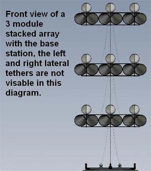 Aerostat’s Airborne Wind Turbine modules contain six turbines. These are attached to the ground base station by tethers. The modules can be stacked in multiple layers, 1,000 ft. apart, beginning at 1,000 ft. and going up to 30,000 ft. |
The Problem
Not all locations are practical or cost effective for ground-based wind-generated energy production. Some locations do not have dependable, consistent wind to drive turbines. Many areas that do enjoy steady wind suffer from periods of high turbulence. To generate energy in these areas, the turbines must be rugged enough to withstand the destructive bursts of wind over their operating life. To meet these structural demands, and still be large enough to produce necessary quantities of electricity, ground-based wind turbine manufacturing costs can be high.
The Solution
The best conditions for wind-turbine operation are 1,000 to 30,000 ft. above ground level. At these altitudes, turbulence is greatly diminished, and wind speed is continuous and stronger than it is on the ground.
For its design, Aerostat uses a tethered blimp, with six-turbine modules attached to the system’s base station. A shroud, or funnel, positioned in front of each turbine, concentrates the wind to higher pressure and velocity. Because the shrouds are suspended in the atmosphere, they can be 10 times larger than similar structures on ground-based systems. At the back of the turbine, a diffuser creates a vacuum that draws out and disperses the wind.
Because each turbine is shrouded, Aerostat was able to reduce the weight, size, and cost of the turbine blades. The blades can be similar in size to those found in a car turbo. The blades can also run at higher speeds, which allowed Aerostat to eliminate the gearbox and achieve greater efficiency.
The turbine modules attached to Aerostat’s AWTs can be stacked in layers 1,000 ft. apart up to 30,000 ft. The blimp self orients into the wind. Electricity is transmitted to the ground via a coaxial tether.
The Impact
The AWT solves one of the major problems blocking the broader use of wind-generated power systems. Regardless of wind conditions on the ground, an airborne platform places the turbines where the wind is continuous and strongest, making the overall system reliable and efficient. This approach makes geographic areas currently unsuitable for wind-generated power systems viable sites for this application.
It does not, however, solve objections relating to appearance and the 500 ft. height limit prescribed by the Federal Aviation Administration. As a result, governmental approval for testing and operation becomes problematic.
More Info:
Aerostat Wind Turbines
Tom Kevan is a New Hampshire-based freelance writer specializing in technology. Send your comments about this article to [email protected].
Subscribe to our FREE magazine, FREE email newsletters or both!
Latest News
About the Author
DE’s editors contribute news and new product announcements to Digital Engineering.
Press releases may be sent to them via [email protected].


