

Latest News
March 30, 2012
By Dimitrios Karamanlidis
Editor’s note: In his April 2012 article, the author provided an overview of the process described in step-by-step detail below. Please see that article here.
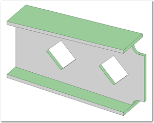
SpaceClaim 1: Create a sketch
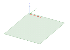
SpaceClaim 2: Use the Pull tool to create a solid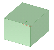
SpaceClaim 3: Switch from Design to Prepare, select the beam profile of your choice, click on Create and then select the edges on which you want the beams to be placed
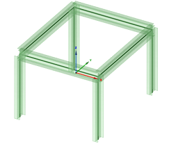
SpaceClaim 4: If you want to change the orientation of any beam, click on Orient, select the beam(s) in question and rotate accordingly. If you wish to modify the beam profile, go to the structure tree on the left pane, expand the Beam Profiles folder, right-click on the current profile and select Edit Beam Profile. That brings up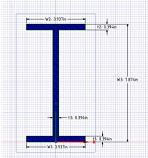
which shows the current profile dimensions.
SpaceClaim 5: Switch back to Design to make whatever changes you desire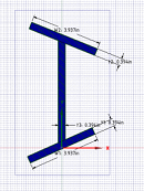
and when you are done just close the sketch. You’ll notice that another tab has been added at the bottom of the editor, indicating that the beam has been saved as a separate part.
SpaceClaim 6: Click on the tab that corresponds to the original (“parent”) solid. The changes you made on the beam profile should now be visible
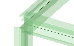
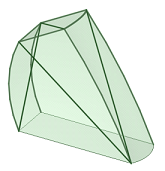
SpaceClaim 7: To make changes to the overall shape of the truss/frame just edit the parent accordingly. For example, if you want to have a sloping top face, just select it and impose a rotation with respect to one of the edges, as shown below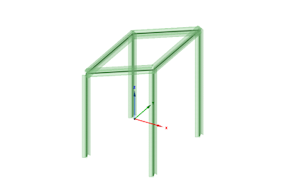
Curved members may be created with the help of the Bend tool (see below)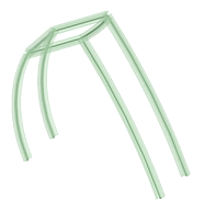
SpaceClaim 8: Concerning diagonal members (“braces”) we have to make a distinction between transferring the file to ANSYS using the API or by way of a geometry neutral file. In the case of the former, all you need to do is create the beams by selecting their respective endpoints. When you migrate to ANSYS everything gets safely transferred and … life is good. Not so in the case of the latter where some gymnastics is necessary due to the fact that beams don’t make it into the geometry file. In what follows I’ll show you one way of getting it done with the explicit understanding that no claim is being made of providing the one and only solution. Let alone the most elegant one.
SC 9: Once the beams have been placed, create a new component under the parent solid and recreate the diagonals using the Project to Sketch tool. Before you export to a geometry file be sure to delete the beam profile from the structure tree else it would be transferred as well
Now before turning the attention to ANSYS, a word of clarification seems in order. The presented example is simple enough to entice someone into thinking “Hey what do I need SpaceClaim for to generate a couple lines? Joe Smoe’s Fabulous CAD could do that !!”. Well folks, relax. It’s just an example. With the software you can create as complicated geometries as your imagination allows you to, for example
 |  |
|---|
On the other hand, it’s really a bummer that anyone who does not have access to the SpaceClaim-ANSYS API has to jump through hoops to get ALL beam centerlines transferred. Here is hope that the good folks at SpaceClaim would reconsider and do something about it in the not so distant future.
ANSYS 1: Now we are off to ANSYS. First we import the geometry file (I chose the IGES format) using the sequence
File > Import > IGES
Typically, you can take all the defaults.
ANSYS 2: Check to see if your geometry model has any volumes and/or areas. If it does, just delete them using the sequences
Preprocessor > Modeling > Delete > Volumes Only
and/or
Preprocessor > Modeling > Delete > Areas Only
ANSYS 3: Get rid of all extraneous lines using the sequence
Preprocessor > Modeling > Delete > Lines Only
ANSYS 4: To make sure that the model has no gaps nor overlaps use the sequences
Preprocessor > Modeling > Operate > Boolean > Glue > Lines > Pick All
Preprocessor > Modeling > Operate > Boolean > Overlap > Lines > Pick All
The result should look similar to the figure below
ANSYS 5: To analyze the structure as a truss choose a 3D truss element from the library using the sequence
ANSYS 6: Define the truss element “real constants” using the sequencePreprocessor > Element Type > Add/Edit/Delete > Add > Link > Spar 8
That brings up the real constants windowPreprocessor > Real Constants > Add/Edit/Delete > Add > OK
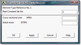
where you enter the pertinent values for the cross-sectional area and the initial strain. The latter is needed only in cases where the structure in question is subject to deformations prior to applying the external loads (e.g., temperature effects, manufacturing errors, etc.). If not all members in the structure have the same properties we need to define the appropriate number of real constant sets. Concerning the cross-sectional area, for a complicated profile we can obtain the numerical value(s) either from SpaceClaim or from ANSYS. In the case of the latter we use the sequence
Preprocessor > Sections > Beam > Common Sections
which will bring up the Beam Tool window
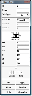
Assuming our cross-section has an I-beam shape we select it from Sub-Type drop down window and then enter the appropriate dimensions. Clicking on Preview will then carry out the computation of all cross-sectional properties. (In the case of a truss we only need the area).
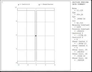
We jot down the numerical value and enter it through the Real Constants menu, as shown before.
ANSYS 7: Define the material properties using the sequence
Preprocessor > Material Props > Material Models
which will bring up a window titled Define Material Model Behavior
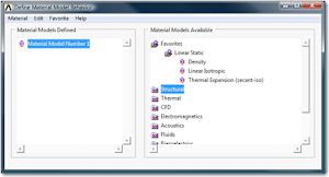
Expand the Favorites folder and click on Linear Isotropic to bring up the window
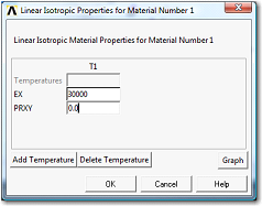
where the numerical values for the modulus of elasticity (EX) and Poisson’s ratio (PRXY) may be entered. We assumed the material to be structural steel and entered for EX=30000 (ksi), and for PRXY=0.0 since in a truss we are only interested in axial stress/strain.
ANSYS 8: Use the sequence
Preprocessor > Meshing > Size Cntrls > ManualSize > Lines > Picked Lines
in order to define size controls for the mesh generation. We first pick the four vertical legs and in the Element Sizes on Picked Lines window
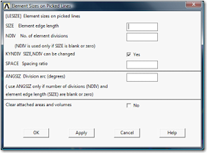
we enter NDIV=3. As a result, each of these lines will be divided into three elements. Next we select the four diagonal braces and specify NDIV=5. And finally the four curved members for which NDIV=8 is entered. Obviously, these numbers are chosen for illustration purposes only and one should not read too much into them.
ANSYS 9: Use the sequence
Preprocessor > Meshing > Mesh > Lines > Pick All
in order to create the element mesh. That concludes the pre-processing phase of the analysis.
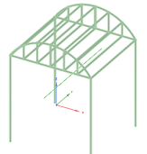
ANSYS 10: The next step is to define boundary conditions and applied loads (cf. figure below)
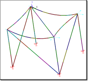
and run the analysis.
ANSYS 11: Once the analysis is completed, the user would proceed with the Postprocessing of the obtained results. Given the multitude of options we are not going to cover this step here.
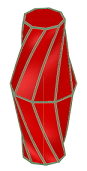
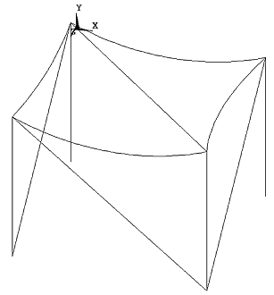
Before wrapping it up let me make one final point. Trusses and frames are quite complex designs and even with all the help provided by SpaceClaim’s Prepare tools it would have taken quite a while to prep up a geometry model for analysis. Hence, to save time we only focused in this tutorial on creating the analytical model directly rather than extracting it from an existing geometry model.
To make the point perhaps a bit more clear, if someone was to come to me and tell me that by using their software I could gofrom this (geometry model)
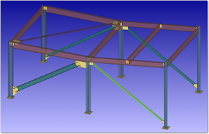
to this (analytical model)
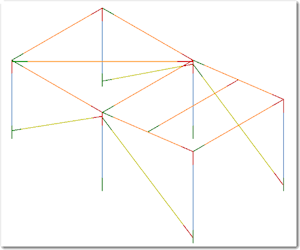
without breaking much of a sweat I would conclude they were trying to take me for a ride. How come? Just take a look at the structure close-ups shown below and you’ll get the idea rather quickly.
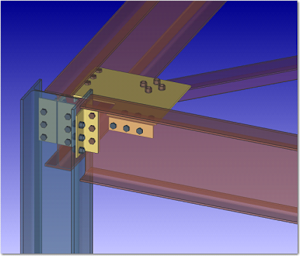 | 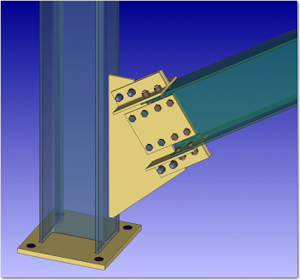 |
|---|---|
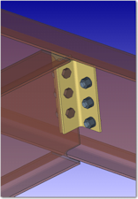 |  |
Subscribe to our FREE magazine, FREE email newsletters or both!
Latest News
About the Author
DE’s editors contribute news and new product announcements to Digital Engineering.
Press releases may be sent to them via [email protected].
Related Topics


