

Latest News
January 1, 2007
By Al Dean
If you look at the products that inhabit our homes and workspace, the majority probably have two things in common. First, if they’ve been developed in the last ten years, they’ve been probably designed using a 3D design system and second, a good percentage of those products will feature some form of PCB (printed circuit board) component.
So, how do you integrate the two key parts to these products — the design of the functional and aesthetic aspects of a product with the development of the PCB components that provides the functionality and intelligence common in many?
The answer is on many levels, and revolves around how you develop your products — but the chances are that the electronic systems and the mechanical/industrial design teams are distinct — and are just as separated as the design systems they use to carry out their own tasks. So, how can you resolve this when there’s seemingly little in the way of compatibility? Well, for those with SolidWorks (and shortly, other systems too), one solution is CircuitWorks, developed by Priware.
CircuitWorks started out life, around 8 years ago, as a simple IDF translation tool for SolidWorks. For those unaware of it, IDF is a neutral file format for storing PCB data, which can be imported and exported by the majority of PCB design systems. There are three versions of the IDF file format currently in use; IDF 2.0, IDF 3.0, and IDF 4.0. The more common IDF 2.0 and 3.0 file formats are comprised of two digital files. The first (the Board file) stores the geometry and other has information about the printed circuit board itself. This includes the geometry of the board, its thickness, any holes (both plated and non-plated) as well as “keep out” or protected areas. The second file (the Library file) contains information about the size, shape, and location of the components on the PCB. The more complex IDF 4.0 format is represented by a single digital file that contains all the information found in the two parts of the IDF 2.0 and 3.0 formats, along with more information about the traces, pads, and filled areas on the PCB.
 |
| CircuitWorks |
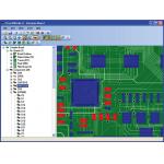
> > CircuitWorks 9 lets you load IDF or PADS data and preview it, filter out components by size, name, height or other property, then reconstruct that data within the workhorse MCAD system.
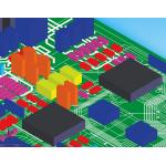
As most IDF files contain height information, it’s possible to build a detailed 3D model of a PCB and its components in an MCAD system using the data in an IDF file. This is what IDF translation tools do — they read the IDF format, build the geometry of the board, create the components, and then position them on the PCB. The end result is a 3D representation of the PCB, which can then be used as part of the product development process, whether that’s to integrate the PCB into the product packaging or to use in thermal analysis, etc.
Priware’s website contains more information about CircuitWorks and the IDF file format. It also has a comprehensive list of the major electronic CAD (ECAD) systems capable of reading and writing IDF files.
What the developers of CircuitWorks realized is that while this linear process is ideal for base-level functionality, many organizations are looking to work a lot more efficiently, particularly when you consider the drive for concurrent product development where the mechanical aspects are being handled at the same time as the electronic design. So, CircuitWorks has been expanded to support this workflow and the complex data interaction — and this release sees much of that work reach fruition.
While CircuitWorks is still fully integrated into SolidWorks, Version 9 sees it also become a stand-alone application that acts as a link between ECAD and MCAD systems (currently SolidWorks, but support for additional MCAD systems will be available soon). By allowing the interface to be used independently of SolidWorks, CircuitWorks is no longer just a tool in the MCAD system — it can now be used to open, view, modify, and save IDF files without the need for an MCAD or ECAD system to be present on the same computer.
The application is cleanly laid out and can read all flavors of IDF file (IDF 2.0, IDF 3.0, and the emergent IDF 4.0) as well as PADS (*.asc) files. When a supported file is opened in CircuitWorks, the data is displayed both as a treeview showing the features such as the board, holes, and components in the file, and as a dynamic preview image that can be panned and zoomed to give a more detailed view of the PCB.
 |
| CircuitWorks |
< < The emerging IDF 4.0 format allows you to exchange a much richer description of the PCB because it supports more complex component geometry descriptions, pins, and traces.
The treeview and preview image allow you to ensure that you have the correct data, but also allow you to modify the data before building it in SolidWorks. Features such as components and holes can be moved or deleted if required, but the real clever stuff is the filtering tools. These allow you to filter out features that are not needed in the 3D design workflow. This might be components filtered out by size, name, or other metadata extracted from the IDF file, or it might be mounting holes or smaller components that are under a specific size and are non-critical to the design process. The point is that you filter out the features you don’t need before importing the data into SolidWorks. As soon as a filter is applied, the preview image and treeview update dynamically to show the results, so you can instantly see what effect your changes have had and what the SolidWorks model is going to look like.
When you’re good to go, the system connects to SolidWorks and starts the process of building the PCB assembly. CircuitWorks first creates a model of the board with any associated holes (and traces, pads, and filled areas in IDF 4.0). Once the board model has been created, the system then creates any component models that are required and inserts them all into an assembly representing the PCB.
IDF files are instance-based, so you might have one component definition that’s reused multiple times in the same PCB, and CircuitWorks uses this to great effect. Rather than model the same component many times, CircuitWorks creates a single model of each component, saves it in its component library, and then places it as many times as is required into the PCB assembly.
If CircuitWorks encounters the same component again in a different IDF file, it will simply re-use the model it already has in its library — saving a huge amount of time. As you use the system more, the more efficient and populated the library becomes. As component shapes in IDF 2.0 and 3.0 files are defined fairly simply by a footprint shape and a height, the component models CircuitWorks produces aren’t very detailed, but are fine for most purposes. If you want to use highly detailed component models in your assembly instead, CircuitWorks’ library allows you to dive in and either modify the models it has created or to simply replace them with more detailed versions. This is useful when you need a very accurate assembly model in SolidWorks where space constraints are very tight, or if you intend to use the final assembly for generating marketing images, for example. The end result is an accurate 3D assembly model of your PCB file that can be used in the product development process.
 |
| CircuitWorks |
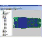
> > Unlike other PCB Importing tools within the SolidWorks market, CircuitWorks lets you work with very heavy datasets — because it handles all of the pre-processing before loading it into the MCAD system.
Now, this type of functionality isn’t unique. But what differentiates CircuitWorks is that while what we’ve described is a one-way process form ECAD to MCAD, CircuitWorks also supports the reverse: SolidWorks parts and assemblies can be saved as IDF files. If you’re working at the formative stages of the design process, the chances are that both the mechanical and electronic designs are going to be in a state of flux. Instead of confusing phone calls or hallway conversations, the mechanical engineer has the ability to move or modify components in the SolidWorks model of the PCB, and then use CircuitWorks to pass that information back to the electronics team as an IDF file — and vice versa. If the engineer receives an updated IDF file, they can also use the integrated comparison tools to find the differences. Priware is looking to make this multidisciplinary way of working even more efficient with the introduction of view and markup tools that allow both parties to use CircuitWorks as the basis for their interactions — but that’s to come.
Those involved with PCBs within the SolidWorks community are probably aware that a cut-down version of CircuitWorks (CircuitWorks Lite) is available in the core SolidWorks product, but this is heavily restricted — it can only import, build a single part of the whole PCB rather than an assembly, and can only be used to process small IDF 2.0 and 3.0 files.
What CircuitWorks does is bring a great deal more intelligence to the process. It does this in terms of viewing, filtering, comparison and library creation tools, but perhaps more importantly, in terms of support for bidirectional data flow between two critical disciplines in the development of many of today’s products.
The latest version of CircuitWorks makes all this much more beneficial, as it can be used outside of SolidWorks, which means by both electronics and mechanical teams as the means for true collaboration. Chances are that whatever your specific industrial sector is, you’re looking to squeeze the most out of your process, and if PCBs are a key component in your products then CircuitWorks can assist in removing bottlenecks that exist in terms of data flow and ensure that everyone involved in the process is working in the most efficient manner possible.
Al Dean is Technology Editor of the UK’s leading product development and manufacturing journal, MCAD and is Editor of Prototype, for the rapid prototyping and direct manufacturing industry, both available by clicking here. Send your comments about this article through e-mail by clicking here. Please reference “CircuitWorks 9” in your message.
Contacts
Priware Ltd.
Much Wenlock, Shropshire, UK
SolidWorks Corp.
Concord, MA
Subscribe to our FREE magazine, FREE email newsletters or both!
Latest News
About the Author
DE’s editors contribute news and new product announcements to Digital Engineering.
Press releases may be sent to them via [email protected].


