

Latest News
May 1, 2012
By Mark Clarkson
|
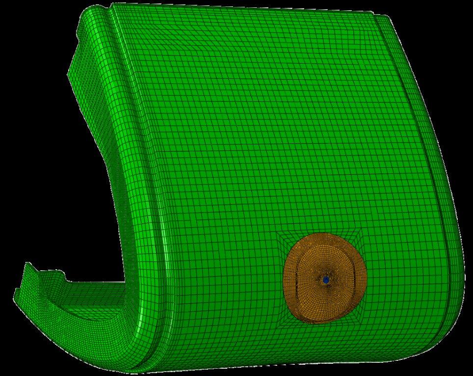
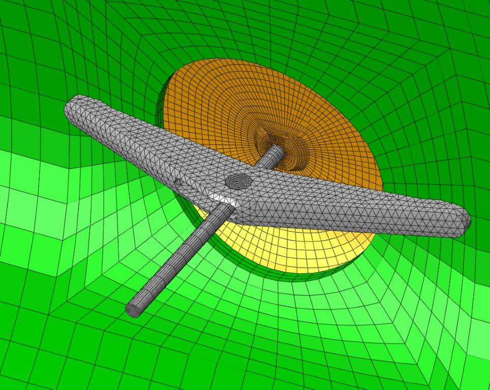
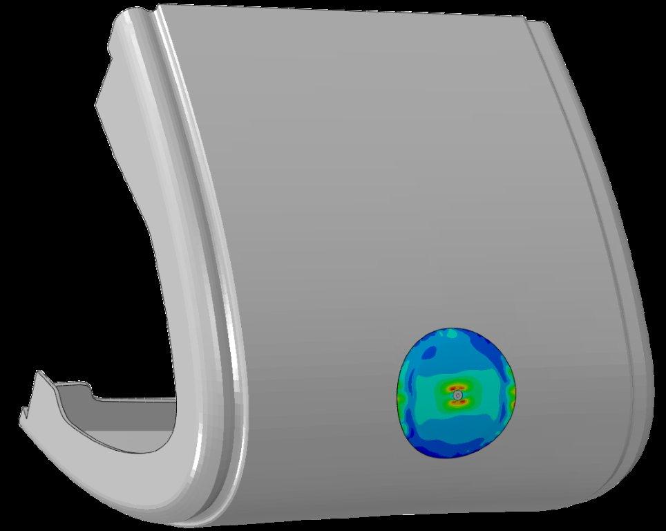
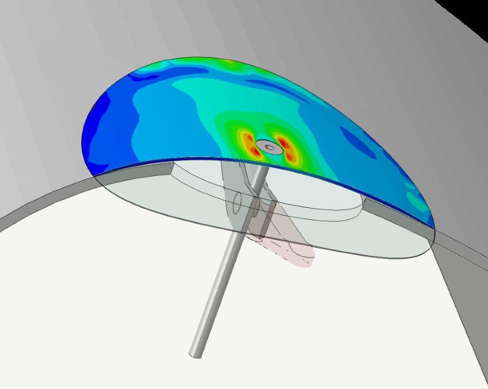
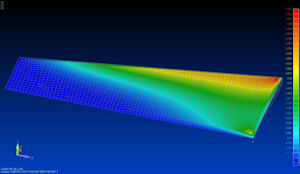
Space Shuttle WLE Contingency Repair Analysis Images These images, are of finite element analysis (FEA) models and analysis results of a reinforced carbon-carbon (RCC) composite wing panel and wing panel patch, which was used on the U.S. Space Shuttle in case orbit repairs were needed. RCC is a specialized composite material that can withstand aero-heating temperatures in excess of 5,000°F.
The Space Shuttle wing leading edge (WLE) repair effort was developed in response to a recommendation by the Columbia Accident Investigation Board (CAIB), which investigated the loss of the orbiter and the STS-107 crew. This investigation revealed the loss of the Columbia and her crew was due to a damaged RCC composite (RCC) WLE component. The objective was to develop an on-orbit repair capability for the wing leading edge in the event it is damaged during future flights. The repair enabled the shuttle to return to Earth in the event of damaged wing panel.
RCC panels formed the WLE of the Space Shuttle. The basic RCC composite is a laminate of woven orthotropic graphite fabric and carbon matrix, with the outer layers converted to silicon carbide in a diffusion coating process. The laminate is constructed in a cross-ply pattern, with the resultant mechanical properties essentially equivalent to the orthogonal directions.
Repair of a hole in the WLE required robust refractory materials that conform to the wing’s surface contour, since re-entry temperatures can be higher than 2,300°F. The repair plug material consists of a carbon silicon carbide (C/SiC) substrate. A T-bar attach mechanism made of TZM (a molybdenum alloy) was used to conform and attach the flexible C/SiC plug to the RCC curved surface.
|
ATK Aerospace Systems builds composite space structures, including solid rocket boosters for the shuttle, rocket motor cases and nozzles. Its commercial launch vehicle, Liberty, is expected to launch next year.
When it comes to building for space, designs are cut to the bone, asserts Nathan Christensen, ATK’s senior manager, engineering tools and analysis.
“In space vehicles,” he says, “you have very low margins of safety. They’re designed right down to the gnat’s eyeball. An unmanned vehicle might have a safety margin of 1.2. A manned vehicle might still only have a 1.5 margin, whereas with an aircraft you’re looking at margins of 4 or 5.”
On top of that, Christensen says, the space industry is a lot more risk-averse than it used to be: “A lot of that has to do with our ability to do simulation. Using tools that we didn’t have 20 or 30 years ago, we’re able to test dozens of different designs ]in the computer] before any of them take physical form.”
Although those designs seem relatively straightforward—cylinders, cones, etc.—there’s a bit more to them than that. Consider the nozzle of a solid rocket motor, for example.
“The throat is composite,” says Christensen. “It’s designed to erode while the rocket fires. The thrust changes with the throat diameter.”
You can’t “de-couple” the fluid and finite element (FE) simulations; each affects the other. Modeling this interaction takes sophisticated tools, which companies like ATK used to develop in-house. “But now,” says Christensen, “you’re seeing commercial tools—like ANSYS multiphysics and Nastran multiphysics—that do that kind of coupled analysis, coupling structure, thermal and fluid flow. It’s cost-effective to use commercial software when we can. We don’t have to invest the resources in software development that we once did.”
The commercial availability of these tools is key to the proliferation of composites in aerospace, because composites are hard to understand.
The Many Modes of Failure
“Composites are unique,” says Stanford Professor Emeritus Stephen Tsai, “in that you have structural behaviors that have no counterpart in homogeneous material.”
It’s much easier to characterize a flaw in a homogenous material, according to Tsai. “For composites, you not only have in-plane failures—matrix failure, fiber failure, interfacial failure—but also out-of-plane failures that involve delamination. The traditional fracture mechanics become much more complicated: You don’t have one crack, you have thousands of cracks, micro-cracks, separation voids and so forth. These require very sophisticated simulations. You can’t do ]the math] on the back of an envelope.”
The Parable of Ironbridge
How did engineers build composite structures without these simulations? Jerad Stack, CEO of Firehole Composites, Laramie, WY, shares an illuminating story: “There’s a place in England called Ironbridge, where humankind built the first iron bridge. We didn’t really know what we were doing. All we knew then was wood, so we used wood engineering.”
The cast iron bridge was built using a modified form of carpentry. It worked. The bridge is still standing 230 years later. But what’s significant is that the bridge was over-designed, using perhaps twice the necessary iron.
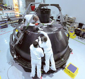 Fabricators at ATK in Iuka, MS, laying up plies of composite material to create the inner honeycomb sandwich skin of the NASA crew module. The plies are being laid up with the assistance of a laser projection system, which is driven by VISTAGY’s FiberSIM software. |
“When composites were new, we were taking tools that we’d been using for decades with metals, and trying to use them for composites, Stack says. “But composite materials are different,” he continues. “They’re not metals. The mechanics behind them are different than aluminum or steel. The fundamental difference is that there are two materials there. Our belief is you have to treat it like two materials, so we have composite-specific tools like our Helius:MCT.”
Embracing Anisotropy
Carbon fiber composites, for example, comprise the carbon fibers themselves and the resin, or matrix, that glues them together. The fibers are usually parallel and unidirectional. As a result, these composites are anisotropic (or orthotropic) materials; they exhibit very different material properties in different directions. They are, generally speaking, strong in the direction of the fibers, and weak in the directions perpendicular to the fibers.
To those used to working with isotropic materials such as metal, the logical response was to stack the composite in layers, or plies, with fibers oriented in different directions. The resulting laminate is reasonably strong in every direction, but it somewhat misses composites’ potential.
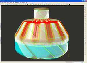 Pictured is a simulation generated by FiberSIM showing how fibers deviate from the specified orientation, as a ply of composite material is draped over a tool for making the NASA composite crew module. The areas highlighted in white indicate fibers whose orientations fall within an acceptable range from specification, while the yellow and red areas indicate where fibers mildly (yellow) or significantly (red) deviate. |
“Many people feel more comfortable and confident with a more uniform composite,” says Dr. Kim Parnell, principal and founder of Parnell Engineering & Consulting, Sunnyvale, CA. Still, he points out, its effective modulus (a measure of stiffness) is “much less than the strong modulus in the fiber direction. Its effective strength is much less.”
By controlling fiber orientation, you can direct a structure’s strength where it’s needed. You’re not just designing a part with the desired properties; you’re designing a material with those properties. You’re exploiting, rather than fighting, the anisotropy.
Composite material properties are also highly dependent on the manufacturing and layup processes. Different manufacturers using the same “recipe” can produce significantly different materials. But there’s opportunity hidden here as well. Composites are customizable. You can create different, finely tuned materials. All of those options can be hard to sort through, but automation can help.
“The real differentiator for us is in the optimization,” says Bob Yancey, executive director, global aerospace, for Altair. “If you know the general shape of the structure, and the loading and boundary conditions, you can set up an optimization problem ]in Altair’s OptiStruct]. How should those ply angles be distributed in the laminate? How many do I need of each ply angle? Where should my laminate be thicker? Where can it be thinner?
“It’ll come back with a proposed design, which is a great conversation piece to get manufacturing, design, stresses and operations all in the same room, talking,” he adds.
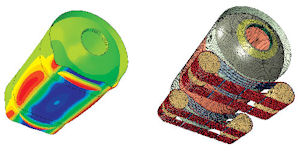 Left: Buckling analysis results and magnified deformation of a filament-wound composite solid rocket motor case sitting in the rotator chock system. Right: 3D FEA model of graphite epoxy filament-wound composite rocket motor case sitting on rotator chock belt system. The rotator chock belt system uses a chain and rubber pads (discretely modeled) for ground-handling operations to prevent composite fiber damage. Image Courtesy of ATK Aerospace Systems; Engineer: M. Gonzalez; Software: NX, Abaqus. |
Progressive Failure
Unlike metals, composites fail progressively. Cracks or delaminations in one area redistribute stresses to adjoining areas, which fail in turn.
“I see progressive failure analysis as the next level of composite analysis,” says NEi Application Engineer Allan Hsu. “It’s a type of lifecycle analysis where you’re concerned about not just how damage happens, but also how much damage the structure can sustain and how it changes over time. Once something starts to fail, how much load can it still sustain?
“NASTRAN and a few other ]applications] do this, but I see it becoming pretty big in the next few years,” he continues.
When You Assume …
Not every component needs to be analyzed down to the individual fibers. Your analysis can assume a homogenous material and still produce useful results.
“The more assumptions you make, the easier it is to do the analysis,” says Kyle Indermuehle, director, aerospace and defense industry, for SIMULIA at Dassault Systemes. “What assumptions do you think you can get away with?”
Take a spacecraft designed to re-enter the atmosphere, he offers as an example. The thermal loads will be tremendous.
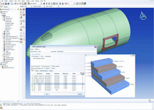 This aeroshell model was created using the intuitive composites layup interface in Abaqus/CAE, which simplifies the definition of composite plies. Abaqus FEA software is then used to analyze the strength of the composite shell and identify potential areas of weakness in critical areas such as windows and access doors. |
“If you’re designing an aircraft,” says Indermuehle, “you could decouple the problem. The thermal loads won’t affect the structure much. For spacecraft, the interaction between thermal and structure are coupled very, very tightly. If you try to decouple them, you’re going to get the wrong answer.”
That answer may only be off by about 15%, but if you’re running on the razor-thin safety margins of the space industry, can you afford it?
The fewer assumptions you make, the more difficult it is to set up and interpret a simulation. You have to define different layers, materials and fiber orientation angles. On the back end, you’ll be studying many more contour plots.
Indermuehle estimates that about 70% of an engineer’s time would be spent building the model; about 20% is spent running the model; and about 10% is spent understanding the results.
“Philosophically, we’d much rather the engineer spend 70% of the time absorbing the results and about 10% of the time developing the model,” he adds. “The technology to solve the problem is there today—the usability is still a challenge, and one we take very seriously.”
 This composite wing model showing stress load paths was created using Altair’s HyperWorks software, using RADIOSS as the solver and OptiStruct to generate the optimized composite structure. |
Simulation is Now King
Understanding composites’ many failure modes requires modern, accurate analytical tools. Previously, manufacturers’ only option was to invest in expensive physical testing and testing was king.
“But that’s not the case anymore,” says ATK’s Christensen, “Now, your test is just a confirmation of your simulation, and the test had better confirm what your simulations showed or you’ve got a lot of explaining to do. Our customers—the U.S. Department of Defense, the Air Force, the Navy, NASA—are very demanding that way.”
Contributing Editor Mark Clarkson is DE’s expert in visualization, computer animation, and graphics. His newest book is Photoshop Elements by Example. Visit him on the web at MarkClarkson.com or send e-mail about this article to [email protected].
MORE INFO
ANSYS
Altair
ATK
Firehole
MSCsoftware
NEi Software
Parnell-Eng
SIMULIA
VISTAGY
Subscribe to our FREE magazine, FREE email newsletters or both!
Latest News
About the Author
Mark ClarksonContributing Editor Mark Clarkson is Digital Engineering’s expert in visualization, computer animation, and graphics. His newest book is Photoshop Elements by Example. Visit him on the web at MarkClarkson.com or send e-mail about this article to [email protected].
Follow DERelated Topics


