3D Printing Offers Design Freedom with New Constraints

Stratasys Direct Manufacturing’s Direct Metal Laser Sintering (DMLS) offerings are helping optimize structures for aerospace applications, including this lighter weight bracketed part. Image courtesy of Stratasys.


Latest News
January 1, 2016
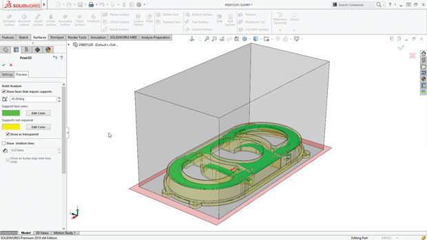 SOLIDWORKS 2016’s Print3D PropertyManager Settings tab includes the ability to change the model scale and to reorient the model to fit the print volume. Image courtesy of SOLIDWORKS.
The dynamic duo of 3D printing and new optimization software is giving engineers the freedom to design and produce organic shapes and lightweight structures that raise the bar on ingenuity while delivering unprecedented savings. Yet to fully reap the benefits of this nicely matched pair, engineers need to master a set of new constraints to ensure designs can be produced in a reliable, cost-effective fashion.
Advances in 3D printing technology—from new materials to higher resolution output capabilities—coupled with topology optimization and other design software improvements are empowering engineers to come up with freeform shapes and complex lattice structures that challenge conventional design limitations. These next-generation designs are not only visually compelling, they are typically more aerodynamic, weigh less and boast fewer parts than designs crafted with traditional CAD tools for output using mainstream manufacturing practices.
While traditional boundaries don’t necessarily apply in the world of 3D printing, engineers expecting an unfettered design environment will be in for a surprise. “In general, the talk about 3D printing technology delivering design freedom without the constraints of traditional manufacturing is true, for the most part,” says Tim Thellin, director of Software and Productivity Tools for Stratasys Direct Manufacturing. “If you know you’re building a part with an additive manufacturing process, you don’t have to worry about undercuts, fillets or internal channels that go deep inside the part. Yet there are different constraints driven by the technology you’re using and the materials you are building with.”
Out With the Old, In With the New
For many 3D printing or additive manufacturing (AM) technologies, the biggest constraint is optimizing designs to minimize or eliminate support structures needed during the actual build process. With certain AM technologies, specifically Direct Metal Laser Sintering (DMLS), there are structural checks to ensure the technology used to build up the part doesn’t actually create stresses that result in part deformation, and ultimately, a bad build. Optimizing a design for the materials used or for proper orientation on the build platform are other factors that need to be considered early on in the process, and there are myriad other constraints that may seem foreign to engineers acclimated to traditional manufacturing processes like casting, injection molding and stamping, experts say.
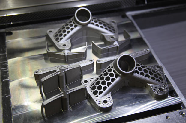 Stratasys Direct Manufacturing’s Direct Metal Laser Sintering (DMLS) offerings are helping optimize structures for aerospace applications, including this lighter weight bracketed part. Image courtesy of Stratasys.
“Design for 3D printing is still in early adulthood,” notes Craig Therrien, senior product portfolio manager at Dassault Systèmes’ SOLIDWORKS. “People think that a 3D-printed part will have the same properties as a casted or forged part, but it doesn’t.” Because 3D printing instills different mechanical properties on a part, it is not an exact science, and Therrien says many engineers compensate by over-designing the part in the hopes of adding rigidity—a tactic that minimizes the lightweighting advantages that make 3D printing such a draw in the first place.
Support structures, in particular, seem to present the biggest design challenges to customers, says Eric Utley, applications specialist at Proto Labs, a digital manufacturing source for custom prototypes and low-volume production parts. Commonly used in AM processes, especially metal technologies, supports are typically scaffold or lattice-type structures required at certain angles to hold a part up as the detailed features are being built. Designing a part so that it steps up incrementally and can be self supporting (instead of featuring long bridges or overhangs) is something engineers untrained in 3D printing techniques don’t necessarily understand, Utley says.Likewise, untrained engineers may design parts with volumes that inadvertently trap powder material from the 3D printing process or have supports that are difficult, if not impossible, to remove. “These constraints are commonplace with organic shapes and with metal AM practices,” Utley says. Education and consulting services are key, he says. “You need to think about support structures as you’re designing. You need to consider what material you want and then look at which 3D printing technology builds in that material. Next you figure out the limitations and design around it. It’s going to be different for each of the 3D printing technologies in terms of what can get by and what can’t,” Utley explains.
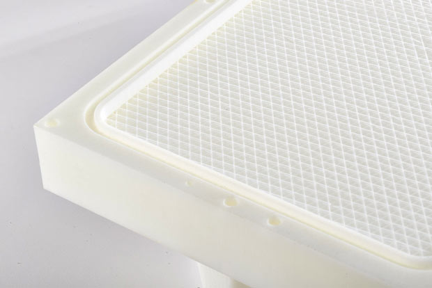 Stratasys’ sparse fill capabilities for its Fused Deposition Modeling (FDM) technology create a honeycomb structure critical for lightweighting parts and accelerating build times. Image courtesy of Stratasys.
Designs that prevent easy support removal, build orientations that don’t work within the build platform, trapped volumes, and issues surrounding wall thicknesses are the biggest mistakes made by BasTech customers, notes Scott Young, engineering manager for the company, which provides AM services. Helping customers work around these inherent design flaws isn’t the problem, Young says, but companies would be better served addressing the issues at the onset of design to avoid additional costs. “It would make life a lot easier and less costly in the end,” he says. “If designers understand things upfront, we can optimize the process and everything goes more smoothly.”
Companies like GE Aviation and Alcoa, which are investing millions of dollars to ramp up their internal AM expertise and perfect 3D printing expertise, are already seeing results. In one of the more highly touted examples, GE completely redesigned its fuel nozzles (19 of them to be exact) on its LEAP engine for Direct Metal Laser Melting (DMLM) processes using EOS systems. The result is a nozzle that is now a single part instead of 20 parts machined together, and it’s far stronger than its predecessor made with traditional subtractive manufacturing processes. “You have to leave behind conventional thoughts and structures when you think in terms of designing for AM,” says Andy Snow, senior vice president of EOS North America, which offers consulting services in how to design for its AM technology.
Software to the Rescue
In recognition of the skills gap, design tool makers 3D printer manufacturers, and simulation software providers are stepping up efforts to provide new services and products to make it easier to design for AM much like any design for manufacturability effort. Stratasys Direct Manufacturing, for example, leverages the Insight software, which automatically slices models to generate support structures and material extrusion paths while also allowing engineers to optimize build orientation for maximum strength. Stratasys’ Fused Deposition Modeling (FDM) technology also allows for sparse fills, a way to print out hollowed or partially filled models optimized to meet cost and weight reduction targets, Thellin says.
There’s lots of activity on the CAD and simulation front. Altair’s topology optimization tools, Inspire from solidThinking Inc. and OptiStruct, are instrumental for creating the organic shapes that AM practices enable, according to Ming Zhou, Altair’s senior vice president of FEA (finite element analysis) and Optimization. To help engineers effectively integrate topology optimization into the early AM design process, Altair has partnered with Materialise to offer its 3-matic STL software to HyperWorks users, allowing them to make design modifications directly on STL, scanned and CAD data in preparation for 3D printing. Moving forward, Zhou says Altair is working to evolve its optimization algorithms to consider overhang angle constraints, supports and print orientation, as well as simulation of printing processes to analyze thermal and material effects. “We’re trying to bring additional cost components into optimization,” he says.
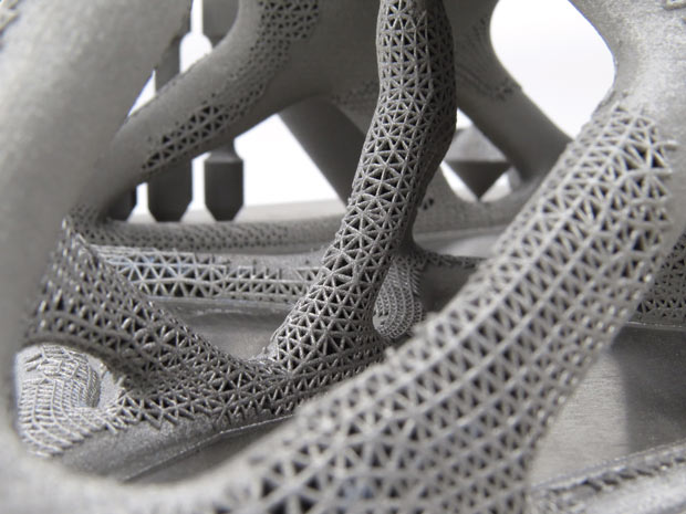 Altair’s topology optimization software has a symbiosis with additive manufacturing, maximizing design freedom to create complex, freeform “bionic” structures. Image courtesy of Renishaw.
Two of this year’s major CAD releases, Autodesk Inventor 2016 and SOLIDWORKS 2016, also feature advances aimed at simplifying design for 3D printing. For example, Autodesk Inventor 2016 and Fusion 360 include 3D Print Studio, a dedicated 3D printing environment that lets users optimize model orientation (even split it in two) for a variety of supported 3D printers. Autodesk also has a lot going on in the area of topology optimization as part of its vision for what it calls “generative design—the concept of starting with a goal and exploring all the possible permutations of the solution until the best one is found.” Shape Generator, available in the latest Inventor update, is a topology optimization function embedded directly in the CAD environment, and Autodesk Within, which automatically generates lattice structures that fit user-defined volumes, is being specifically positioned to help optimize designs for AM.
SOLIDWORKS 2016 now features the Print3D Property Manager Settings tab that enables engineers to change model scale or reorient models to fit in a build volume. A preview tab also lets users run a preview analysis to identify faces that require supports during 3D printing, and the software will display striation lines resulting from layering so users can determine whether the print resolution is optimized enough for the desired output, according to Therrien.
Beyond these capabilities, Therrien sees simulation software evolving to help engineers check the function of a 3D-printed part much like they do now for an injection molded part. “One of the next steps is verifying what we are making because 3D printing is repeatable,” he says. “That’s something that will come in the future.”
One company looking to the future of AM is 3DSim. The startup is leveraging years of research work in AM along with supercomputing capabilities to provide fast and actionable insight into metal 3D printing processes. The idea, according to CEO Brent Stucker, is to help organizations eliminate the waste and reduce the costs of AM practices by predicting residual stress and strain, minimizing the amount of support materials and post-processing finishing work. ExaSim, targeted for release in the second half of 2016, is a whole new set of simulation tools targeted at the machine operator and designed as a guide for helping them build a part properly. The software, which will run in the cloud, takes some of the mystery out of 3D printing processes.
“It takes a long time for someone to learn the physics of what’s going on,” Stucker explains. “Every time you put new geometry on a new machine and create a new scan pattern or vector, you produce a different microstructure and you can’t treat it as a black box.”
With ExaSim, Stucker is trying to turn what seems like a random process into something repeatable. “People spend a lot of time on trial and error experiments to try to satisfy their curiosity or to get a part qualified,” he says. “We’re trying to achieve a dramatic reduction in that time.”
Subscribe to our FREE magazine, FREE email newsletters or both!
Latest News
About the Author
Beth Stackpole is a contributing editor to Digital Engineering. Send e-mail about this article to [email protected].
Follow DE

