Designing Fuel Cells for the Future
Design for Manufacture and Assembly software from Boothroyd Dewhurst helps evaluate designs for automotive hydrogen fuel cell systems.


Latest News
November 9, 2007
By Russell Shuba
 This is an exploded view of a fuel cell stack abridged to two cells for visual clarity.The high number of plates in the hydrogen system made them a key subject for design formanufacture analysis and cost reduction. |
How do you create and cost a detailed, realistic design using components and processes that don’t exist yet? That was the challenge facing Directed Technologies, Inc. (DTI) of Arlington, VA, when the Department of Energy (DOE) contracted the company to design automotive hydrogen fuel cell systems — as they might be built in 2006, 2010, and 2015.
According to the Department of Energy, the polymer electrolyte membrane (PEM) fuel cell — a.k.a. proton exchange membrane — is typically used in automobiles and uses hydrogen fuel and oxygen from the air to produce electricity. Hydrogen is channeled through plates to an anode while oxygen is channeled to a cathode. At the anode, a platinum catalyst splits the hydrogen into protons and electrons and a PEM, which separates the anode and cathode, will only let protons through so the electrons must travel along a circuit to reach the cathode, creating current. At the cathode, the electrons and protons combine with oxygen to form water, which then flows out of the cell. To produce enough electricity to power a vehicle, however, multiple cells are assembled into a stack.
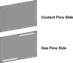 Above is a design for an injection-molded bipolar plate from a hydrogen fuel cell stack. An important challenge at Directed Technologies was determining, through DFMA software analyses,what would be the most costeffectivemanufacturing process for the part. |
Setting Real Targets
DTI, a technical consulting firm that evaluates new and emerging technologies for the government and industry, has researched hydrogen infrastructures and applications since the early 1990s. Previous projects have included reformer technology and cost-effective fuel cells.
In March of 2006, DTI began a two-year study for the DOE as part of an ongoing effort to explore alternative fuels. The goal of the study was to estimate production costs for direct hydrogen proton exchange membrane (PEM) fuel cell systems for use onboard automobiles. The government also set technical targets for each of the 2006, 2010, and 2015 versions.
“The targets didn’t directly drive our analyses,” says Jeff Kalinoski, an engineer at DTI. “Instead, we used our work to evaluate how realistic the targets were.”
To create the three systems, the engineers at DTI are using process modeling software called HYSYS (a package from Aspen Technology for simulating chemical processes and the equipment required for them), computer-aided design tools from SolidWorks of Concord, MA, and Design for Manufacture and Assembly (DFMA) software from Boothroyd Dewhurst, Inc. of Wakefield, RI.
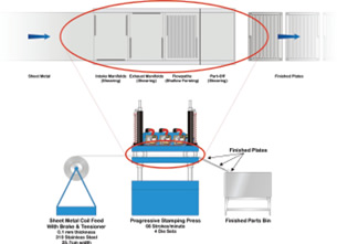 Shown is a progressive stamping press for making steel bipolar plates.The press creates finished parts in four stages (left to right): two shearing stages for intake and exhaust manifolds, a shallow forming stage for flow paths, and a part-off stage to cut the finished part off. A DFMA software analysisfound that this method was the most cost-effective for creating plates at all production volumes. |
Optimum Designs for Fuel Cells
Engineers on the DTI team possess a wide range of expertise, including chemical, aerospace, and mechanical engineering knowledge. Communication between disciplines is maintained using a carefully planned work process. “Our design and analysis methodology was rigorous and time-tested,” Kalinoski says, explaining that work for modeling the fuel cell system falls into four stages.
The research stage involves reviewing literature, looking up patents, and interviewing and speaking with engineers and experts. Throughout this phase, which continues throughout the life of the project, the team is examining hundreds of assumptions behind the construction and the materials selection of a complete hydrogen power system.
A second stage, system modeling, was completed for the 2006 system using HYSYS. The software enabled DTI to establish a detailed model based on technical parameters and to establish specifications and a bill of materials for the system. The engineers involved in this phase then extrapolated technology and process improvements from the same model to come up with bills of materials for the 2010 and 2015 systems.
Component design represented the next stage. This step uses the system model and bill of materials as a basis for modeling all components in 3D using SolidWorks, with enough detail for accurate costing. “Since we were costing a design, not building it, we didn’t have to address every single consideration,” Kalinoski points out. “We designed pipes to handle flow, but we didn’t worry about whether flow was turbulent or laminar. Knowing the diameter, thickness, shape, and materials was enough.”
For its final stage, the DTI design team applies DFMA software and methodology to cost their system thoroughly and to select optimum designs and processes for manufacturing individual components.
DFMA and Design Costing
DFMA software is based on two interlocking approaches: design for assembly (DFA) and design for manufacturing (DFM). DFA guides engineers to evaluate the functional purpose of each assembly component in a conceptual design, helping them simplify the design. DFM identifies and calculates the cost drivers associated with manufacturing and finishing parts in alternative processes.
In DFM, concurrent costing tools enable engineers to determine the most cost-effective process and, in some cases, to alter design features and further reduce costs. The software contains an extensive library of data for varied materials and processes, including secondary machining. A key benefit of DFM software is the quick generation of an initial cost estimate at any stage of design in just a few simple steps.
A DFM analysis was particularly important in choosing a manufacturing process for the bipolar plates of the fuel cells. “We had to cost out the manufacturing process carefully,” Kalinoski says, “since there are nearly 800 plates in each hydrogen system.” A previous study using DFMA software had concluded that injection-molded composite plates were the best process. For the new study, the team re-examined injection molding closely with the software. “We looked at the process in detail, redesigning the plates, changing the number of platens in the mold, and generating costs for different batch sizes,” Kalinoski says.
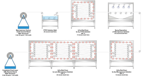 This is an illustration of the manufacturing process for creating the gas diffusion layer (GDL) of the fuel cell stack. The process diagram shows the applicationof a microporous layer on top of the macroporous layer.The process was analyzed for efficiency and cost using Boothroyd Dewhurst DFMA software. |
Comparing Options
This time around, stamped steel plates seemed an attractive possibility. Steel is ideal for stamping because of its strength, high strain rate, and low cost. The DTI team conducted press-force calculations based on the geometry of the plate, and they used the results to size presses for different stamping methods. Once the engineers had selected press types, they used DFMA software to compare multistage, compound, turret, and progressive dies at multiple batch sizes and annual rates.
The results suggest that a four-stage progressive die was the most cost-effective option at all production levels the team considered. There are two shearing stages for intake and exhaust manifolds, a shallow forming stage for flow paths, and a part-off stage to cut off the finished part. The team also performed similar calculations based on their own costing methodologies, then consulted with two outside manufacturing companies to verify that their results were accurate.
The choice of the process guided alterations in the final part design. The plate now has straight, parallel sides and is stamped from a steel roll the exact width of the plate so that the final die stage cuts it with zero waste. The progressive die can produce up to 80 plates per minute.
The design and process analyses yielded some surprises. For instance, the PEM required layers of catalyst on either side of it. The team explored coating the membrane with catalyst on both sides at once for manufacturing efficiency at high-volume production.
Kalinoski points out, “When it came to reviewing low-end production, we had a $750,000 coating machine that we were only running at 12 percent capacity. But DFMA calculations showed us that even at that rate, it was still more efficient than the other processes we examined.”
The Road Ahead
As of October 2007, the study is two-thirds complete and is going well. “We came close to the cost targets the DOE specified,” Kalinoski says, “though there is more to be done.” The DOE set a 2006 fuel cell stack cost target of $70/kW, and DTI estimates a cost of $67/kW. So far, the 2015 stack stands at $25/kW. The DOE was hoping for $15/kW.
Between now and February of 2008, the DTI team will continue tweaking its designs to see if there are any other costs they can remove from their future fuel cell stacks and from the overall system. For example, they will examine alternate manufacturing methods for the proton exchange membrane and the gas diffusion layers, both significant cost elements. Also, they will explore replacing the pure
platinum catalyst with a less-expensive platinum compound.
More Information
HYSYS
Aspen Technology
Burlington, MA
aspentech.com
DFMA
Boothroyd Dewhurst, Inc.
Wakefield, RI
dfma.com
Directed Technologies, Inc.
Arlington, VA
directedtechnologies.com
Department of Energy
Washington, DC
fueleconomy.gov/feg/fcv_PEM.shtml
SolidWorks
Concord, MA
solidworks.com
Russell Shuba is a freelance writer who lives outside Madison, WI. When he’s not tracking down the details of his latest assignment, he can be found plying the north country’s lakes in a homemade kayak or skiing in the backcountry. To comment on this article, send an e-mail addressed to DE-Editorsmailto:[email protected].
Subscribe to our FREE magazine, FREE email newsletters or both!
Latest News
About the Author
DE’s editors contribute news and new product announcements to Digital Engineering.
Press releases may be sent to them via [email protected].


