

August 1, 2010
By Andy Manning
Patients in hospital isolation rooms constantly produce transmissible airborne organisms by coughing, sneezing, speaking or even just breathing. These actions, if not under control, commonly result in spreading airborne infection. In severe cases, such as the transmission of mycobacterium tuberculosis (TB), the consequences of exposure for the caregivers and visitors in particular can be extremely serious.
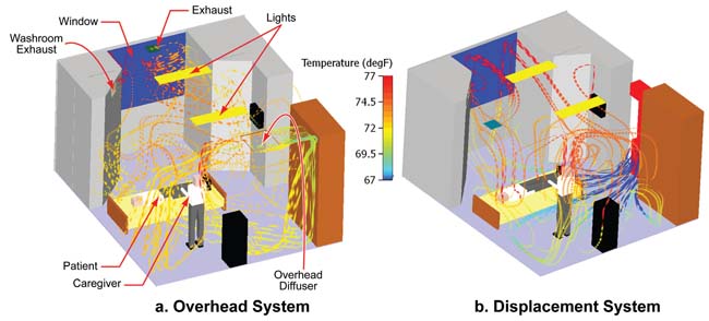 Figure 1: Contrasting two ventilation schemes in a conventional patient room. The displacement system delivers effectiveness similar to that of the overhead system, but with a lower ACH value. |
The designer of ventilation systems for patient rooms needs to be conscious of these contaminant threats, and should account for them appropriately. It is impractical to completely isolate the patient using solid barriers, particularly for less severe cases. The ventilation system itself, therefore, has to act as one of the primary control mechanisms in the room. This can be done in two ways: precise targeting and control of the contaminant source; or creating high levels of mixing, which leads to increased removal effectiveness and can be potentially supplemented by other mechanisms such as ultraviolet germicidal irradiation (UVGI).
The design approach must take into account the primary function of the room. Standards such as American Society of Heating, Refrigerating and Air-Conditioning Engineers (ASHRAE) Standard 170-2008 outline the minimum air changes per hour (ACH), pressurization relationship to adjacent areas, relative humidity (RH), etc., for a range of health care facilities. However, it’s imperative for the designer to use supplemental analysis techniques to ensure that the ventilation system outlined by these guidelines is able to adequately provide control. Put simply, it is not enough to just apply a given ACH to a patient room and expect that it will perform correctly—regardless of the ventilation system design.
Software-based computational fluid dynamics (CFD) tools, such as Mentor Graphics’ FloVENT, allow designers to consider a range of different ventilation system layouts before installation in the physical room, and allow determination of the impact of parametric changes quickly, efficiently and cost-effectively. Several CFD studies (cited in the references section of this article) have addressed patient rooms. The balance of this article discusses the results of several CFD analyses, and explains the kind of design recommendations that can be derived from them.
A View into a Room
CFD analysis has become the tool of choice for evaluating air handling in all kinds of structures and rooms. “Virtual” rooms and airflows have been validated, with good correlation against experimental (physically measured) data. Today it is common for designers to model the flow behaviors of several ventilation approaches to determine that which provides the best performance—from the standpoint of not only patients, but also others who enter the room, however briefly. Two fundamental ventilation system approaches—namely, overhead and displacement diffuser systems—are common in most hospitals.
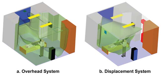 Figure 2: The overall ventilation effectiveness increases when the return grille is located on the side wall, closer to the patient. |
Figure 1 depicts two views of a typical patient room. The annotations point out the room’s standard features such as a patient bed, windows, exhausts, lighting, etc. The overhead ventilation system in Figure 1a meets ASHRAE Standard 170-2008. The room has an overhead ceiling supply diffuser, and high- and low-exhaust locations. The ACH in this case is 6 ACH, and the exhaust flow rate is relatively evenly split between the ceiling and washroom returns. The ceiling return is situated next to the window in this instance. The contaminant source in this case is assumed to be the patient’s regular respiratory function.
In a model-based design environment, changes to the ventilation system and room environment can be applied and analyzed. Parametric changes might include diffuser type and location; outside weather conditions; air change rate; supply temperature; auxiliary heating and cooling systems such as radiant cooling or heating panels, baseboard heaters; solar loading; ceiling height and more.
Models can also assess standard measures of the ventilation system’s performance with respect to contaminant removal and control. Appropriate indices include:
- VE: Ventilation Effectiveness (ASHRAE 62.1 - 2007)
- PEI: Personal Exposure Index, a measure of the contaminant concentration in the breathing zone of a particular individual
- ACE: Air Change Effectiveness (ASHRAE 129-1997)
- ADE: Air Distribution Effectiveness1, applicable specifically to displacement ventilation systems.
Figure 1a shows the flow pattern in a room with an overhead system and how it compares with a displacement ventilation system (Figure 1b) providing 4 ACH. While the flow patterns produced are obviously different, the actual performance of the ventilation system, as measured using the indices above, is very similar. The use of the displacement system, therefore, can be considered as a viable alternative to the overhead system, and can operate at a lower ACH value. The impact of this is the possibility of reducing energy costs through reduced supply capacity.
 Figure 3: This analysis explores the effect of UV light working in conjunction with ventilation to reduce viable TB particles in an isolation suite. |
Again using the modeling environment, some new constraints can be applied to the first-round recommendations. For example, a follow-up analysis tests the notion of using baseboard heaters in the room. The CFD tool confirms that baseboard heaters are acceptable, because the interaction between the heater plume and general airflow (tracked by vectors similar to those in Figure 1) is well away from the patient. At the same time, the analysis reveals that the impact of solar loading is more damaging, and should be avoided.
An alternative proposal is to increase the supply temperature so that the ventilation system can be used as the heating mechanism. However, the analysis concludes that the flow rises immediately upon exiting the diffuser and does not penetrate into the room. Clearly, this is unsatisfactory. A timely discovery such as this can save many hours of trial-and-error design and experimentation.
The final piece of design information here is that the location of the return grille is of crucial importance to contaminant control. In particular, the CFD analysis suggests that the ventilation effectiveness increases when the return grille is located closer to the patient, and decreases when it is located farther away. This is readily evident in Figure 2a and 2b, showing the 3ppm concentration isosurface for the overhead case and displacement cases, respectively, when the return grille is moved to the sidewall. In the former case, the isosurface clearly fills the entire volume of the room, while in the latter, there is a cleaner zone away from the patient bed, especially in the visitor area.
Isolation Rooms and Energy Savings
When the task becomes one of designing an isolation room, the priorities go beyond simply changing the air in the room with a predictable frequency. In such a situation, increasing the ACH is not enough. CFD analysis can help designers evaluate the use of UVGI as a means of reducing the number of viable TB particles in an isolation room2. The particles are usually emitted by coughing, and tend to disperse all around the patient and bed.
The design emphasis is on ensuring that the conditions provided by the ventilation system within the room are well mixed. In particular, the ventilation system must effectively remove the viable particles—both through room exhaust and by subjecting the particles to prolonged exposure to the UVGI field created by the lamps in the room.
Figure 3 depicts the floor plan of an isolation suite of the type commonly found in modern hospitals. The suite consists of three rooms connected via door openings between them. The main room is equipped with four slot diffusers near the window, and a low induction diffuser on the ceiling. As with the “standard” room described earlier, the CFD toolset enables the designer to expediently change mechanical and environmental parameters.
In this case, the set of parametric changes touched both mechanical and environmental variables: the supply flow rate (2 ACH to 16 ACH); weather conditions, both summer and winter (with appropriate supply temperature settings); and the ventilation system with low exhausts, high exhausts and low exhausts with baseboard heating for winter cases. The UV lamp, located on the partition between the isolation room and vestibule, was evaluated with UV outputs of 10, 20 and 40W. Figure 3 shows the UV field for the 10W lamp.
The upper graph (a) plots the variation in the number of viable particles over time for the summer cases. These curves show that the increase in ACH beyond 6 ACH is a waste of supply flow capacity; that there is little benefit in supplying large values of ACH to the room. Knowing this, the designer can reduce energy use and operating costs during the summer load conditions.
The lower graph (b) in Figure 3 reveals the benefit of adding baseboard heating to the room. In particular, heaters help to increase the mixing in the room, and thereby increase the likelihood that the particles will be removed via the ventilation system or killed via the UVGI. The potential saving in energy cost is large, even with the added costs associated with the heaters and UVGI lamps. This is because the recommended ACH is reduced by as much as 50%, to 6 ACH when the heaters are used—compared with 10 to 12 ACH without the baseboard heating.
These are just some of the evaluations that demonstrate the benefits of using CFD tools to numerically analyze the contaminant control in patient rooms. Lower values of ACH can be shown to work just as effectively as higher values, and can lead to reductions in energy operating costs, while the optimization of supply and/or exhaust locations can improve the contaminant control in general.
More Info:
American Society of Heating, Refrigerating and Air-Conditioning Engineers
Mentor Graphics
References
For more information on contaminant control, check out these resources:
- ASHRAE Handbook, Fundamentals, 2009. Atlanta: American Society of Heating, Refrigerating and Air-Conditioning Engineers, Inc.
- ASHRAE Standard 62.1-2007. Atlanta: American Society of Heating, Refrigerating and Air-Conditioning Engineers, Inc.
- ASHRAE Standard 129-1997. Atlanta: American Society of Heating, Refrigerating and Air-Conditioning Engineers, Inc.
- ASHRAE Standard 170-2008. Atlanta: American Society of Heating, Refrigerating and Air-Conditioning Engineers, Inc.
- Lee, K.S., Jiang, Z., and Chen, Q. 2009. “Air Distribution Effectiveness with Stratified Air Distribution Systems (RP-1373),” ASHRAE Transactions, 115(2).
- Memarzadeh F. and Jiang J. 2000. “Methodology for Minimizing Risk from Airborne Organisms in Hospital Isolation Rooms,” ASHRAE Transactions, 106, (2), pp733-749.
- Yin, Y., Xu, W., Gupta, J., Guity, A., Marmion, P., Manning, A., Gulick, B., Zhang, X., and Chen, Q. 2009. “Comparative Study on Displacement and Mixing Ventilation in a Patient Ward,” 2009 International Conference and Exhibition on Healthy Facility Planning, Design and Construction (PDC), Phoenix.
Andy Manning is director of thermal engineering for the Mechanical Analysis Division of Mentor Graphics Corp.
Lee, K.S., Jiang, Z., and Chen, Q. 2009 “Air Distribution Effectiveness with Stratified Air Distribution Systems”
Memarzadeh F. and Jiang J: (2000). “Methodology for Minimizing Risk from Airborne Organisms in Hospital Isolation Rooms”
Subscribe to our FREE magazine, FREE email newsletters or both!
About the Author
DE’s editors contribute news and new product announcements to Digital Engineering.
Press releases may be sent to them via [email protected].


