Digital Prototyping with Autodesk
Costs can be saved via fewer prototypes, faster design validation, less material waste, more accurate quotes, and risk mitigation.


Latest News
August 1, 2010
By Eric Schubert
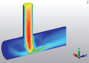 Fluid flow analysis through a pipe connection. Streamlines show added detail. |
In today’s manufacturing community, the topic of simulation has been receiving increased attention from companies making consumer products, industrial equipment, sporting goods among other things. But what is it about simulation that provides such a benefit to these industries? Who should use simulation products? And why is simulation changing the engineering world?
The term “simulation” refers to a computer analysis of what a part or assembly will do when subjected to real-world conditions, and it is a very important aspect of digital prototyping. Digital prototypes are more than just three-dimensional models; they offer numerous advantages, including simulation for design teams. But what can the process of simulation do for the engineering process above and beyond rendering a 3D model?
Production of physical prototypes, whether accomplished in-house or through contracting/outsourcing, can be very expensive in both time and labor costs. If any destructive testing is involved, then multiple prototypes will almost certainly be needed, thereby increasing these costs even further.
Digital models made during the design process, however, can be repurposed to run analyses without a need for physical prototypes. Current finite element analysis (FEA) software allows a broad range of testing that can be performed on these digital prototypes -from simple stress analysis to more advanced functions such as fatigue, impact, vibration, thermal, electrical, and fluid flow analysis. Consider the recent trend of parts being overdesigned to ensure safety, which results in wasted material and increased cost to the company. Alternatively, a good FEA package can provide insight into a product early in the design phase to help maximize design efficiency and reduce material costs.
Autodesk Inventor for FEA
At MasterGraphics, we use Autodesk Inventor Simulation, which includes basic FEA tools right in the software for performing stress analysis. This available FEA allows a designer to test the model under anticipated loading conditions. When using Inventor, this can be done an environment familiar to designers. The integration of FEA into Inventor is beneficial for simple linear stress and frequency response analysis. It also means that the parameters used to construct the model can be varied directly within the simulation environment to test multiple configurations, materials or thicknesses, and to find the most efficient and effective design. The lack of need for translation and the familiar interface mean the learning curve for Inventor Simulation comes easily for current Inventor users.
Material choices tend to bring an element of complexity to the table. There are thousands of different materials available these days, so how can you be sure you’ve chosen the best one for the job? A solid study of material characteristics will certainly help (you can easily eliminate materials that don’t meet specifications for your application), but there will likely be a range of different plastics, alloys, composites and the like that could still be in the running.
Physically testing each of these materials can be quite costly. Using a simulation tool to test each material type can help eliminate poor choices for a given application and improve the characteristics of a component by discovering a stronger, lighter, more cost-effective material to perform the job. These software tools help to eliminate most of the confusion around material choices and help to reduce wasted prototypes and time spent on testing each potential candidate material.
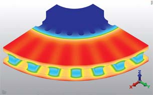 Stress analysis on a disc brake placed under a thermal load shows dissipation of heat away from the outer face throughout the model. |
Stand-alone FEA
Sometimes the need for a higher-end simulation product is required. Autodesk Algor has been around more than two decades, and it was recently acquired by Autodesk and integrated into their overall Digital Prototyping portfolio. Standalone FEA tools, like Algor, offer significantly more features and benefits than the basic tools in Inventor. Four different Algor products (simulation, mechanical event simulation, computational fluid dynamics and multiphysics) provide tools that can run simulations for non-linear stress models (like rubber or silicone), fluid flow analysis, permanent material deformation, and electrostatic analysis—all of which can be coupled with thermal analysis to combine multiple simulations for more complex design scenarios. These additional capabilities can be valuable to companies producing medical and safety equipment, performing earthquake-proofing, making machinery, automotive and aerospace industries, and a variety of other applications. Because many customers are requiring performance validation before contracts are signed, having the capability to analyze an assembly and predict performance can be quite a boon to winning a large deal. There is truly something for every application in the simulation world.
Autodesk also provides its Dynamic Simulation environment within Inventor to test kinematics in assemblies. These simulations can discover the types of stresses, torques, or forces that will be introduced during motion. As the assembly is animated, the points of interest can be monitored on an output graph and maximum or minimum values can be found. While the Dynamic Simulation environment does not perform stress analysis, it can reveal what the forces would be in an FEA model and can export those forces directly over to a stress analysis. A Dynamic Simulation run can also be used to size motors or actuators for moving components. A kinematic analysis of an assembly can be a great way to discover information about a design’s inner workings and find out what forces should be when setting up a finite element analysis.
Pre-analyzing Failures
Risk is always a topic of concern when designing a product. Designers must consider what would be considered a “failure” during intended use of a part or assembly. Is “failure” considered a fracture or buckling of a key component? Perhaps “failure” is simply too large of a deflection value. Simulation products provide methods to determine when and where a component will fail.
The analysis will indicate high-stress or high-deflection regions to point out areas where ribs or supports should be added to provide additional strength. The accompanying documentation of initial analyses also bring some measure of protection against any legal issues that may arise, which may bring into question the validity of a design or safety of a product. Mitigating any significant risk factors in a design can be crucial for a product’s success in the marketplace.
The benefits of using simulation products are enormous. When manufacturing or designing any product, the chances are very good that simulation tools can be used to enhance and streamline the design process.
More Info:
Autodesk
MasterGraphics
Eric Schubert joined MasterGraphics in 2005, specializing in the manufacturing industry. As an application engineer, Schubert assists manufacturing companies with implementing Autodesk Inventor Simulation and Autodesk Algor solutions, also providing post-implementation support and training. Please send comments about this article to [email protected].
Subscribe to our FREE magazine, FREE email newsletters or both!
Latest News
About the Author
DE’s editors contribute news and new product announcements to Digital Engineering.
Press releases may be sent to them via [email protected].


