

April 1, 2012
By Kenneth Wong
Editor’s note: Read part 2 of this article here. To read all of the articles in DE‘s recent series on direct modeling, click here.
Do you know that simulation and analysis experts routinely perform cosmetic surgery on CAD models? Before they load a model into finite element analysis (FEA) software, they often strip the model of unnecessary details. Cosmetic features that make a design look pleasant but don’t serve any practical purpose, like rounded corners, would have to go. Next to go are minor features that do serve a purpose, but don’t make a difference in stress and load distribution, like small holes. Removing these details simplify the geometry, reducing it to its basic building blocks. This goes a long way toward reducing the time required to mesh the model.
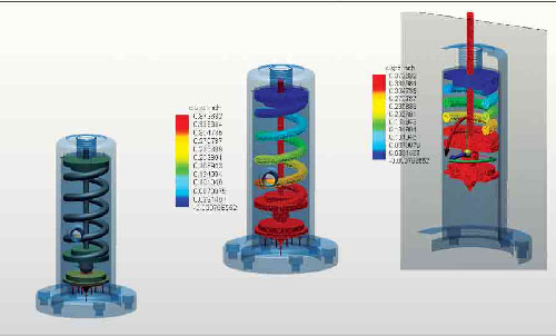
With the launch of KeyCreator 2012, Kubotek begins offering KeyCreator Analysis, an FEA program nested inside a direct modeler. The module allows you to run flow and thermal analysis, then adjust the geometry to refine your design based on analysis results.
Surfaces with curvatures take more time to subdivide, so if you have too many of them, your meshing time increases exponentially. Conversely, primitive shapes like squares and cylinders are easier to subdivide, so the simpler the design, the faster it is to mesh and solve.
But a history-based CAD program may not be the best environment to make the geometry edits mentioned above. Because of its adherence to feature history, or the sequential steps in which the model is created, history-based CAD programs don’t allow deleting or removing features on a whim. To delete a feature in a history-based CAD modeler, you would have to identify the step previously used to create the feature, then make the edit—a daunting task for simulation and analysis experts who are not necessarily CAD experts.
In the resurgence of direct modelers, analysis and simulation experts found a better alternative. Because a direct modeler allows you to modify CAD geometry without concerns for its construction history, it’s often the preferred choice in performing the geometry edits required to prepare a design for FEA. The matchmaking has already begun, as seen in the pairings of SpaceClaim and ANSYS (see the related article here), and KeyCreator and AMPS. More will likely follow.
A Brief History
In October 1995, HP published an article titled “HP PE/SolidDesigner, Dynamic Modeling for Three-Dimensional Computer-Aided Design” (HP Journal, October 1995). Authors Klaus-Peter Fahlbusch and Thomas D. Roser wrote, “HP Precision Engineering SolidDesigner (PC/SolidDesigner) is a 3D solid modeling design system based on the ACIS Kernel … The system’s dynamic modeling technology gives the designer the freedom to incorporate changes at any time and at any stage of product development, without dependence on the history of the product design … It supports the coexistence of surface data with solid data, and provides the ability to import and modify surface and solid design data from a variety of CAD systems … The flexible, non-history-based, intuitive design technique provides direct interaction with modeling tools and designs …” It was one of the earlier examples of a direct modeler.
Subsequently, SolidDesigner evolved into CoCreate, now owned and marketed by PTC as Creo Elements/Direct Modeling. In the late ’90s, IronCAD LLC and Kubotek joined the direct modeling market with their products, IronCAD and CADKey, respectively. Although some manufacturers adopted the technology, the majority continued to rely on traditional history-based modelers, such as SolidWorks, Solid Edge, Autodesk Inventor, NX and CATIA. The birth of SpaceClaim in 2007, however, prompted many to re-examine the role of direct modeling.
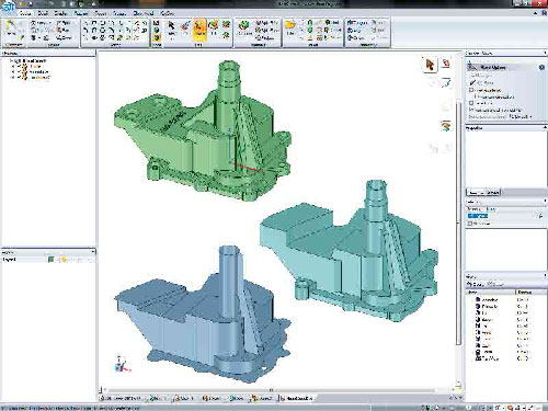
In a direct modeler like SpaceClaim, removing cosmetic details to prepare a model for analysis is much easier than performing the same operations in a history-based modeler.
By reducing direct modeling into a series of pushing, pulling and rotations, SpaceClaim managed to popularize a technology that has been around for more than a decade. Its swift penetration into a market dominated by history-based modelers forced history-based CAD software developers to take a second look at direct modeling. The outcome was Autodesk’s introduction of Inventor Fusion, Siemens PLM Software’s debut of Synchronous Technology, and PTC’s renewed efforts to refine Creo Elements/Direct Modeling. (For more on the difference between direct modeling and history-based modeling, read “We Gather Here Today to Reconcile Direct and Parametric,” March 2012, at deskeng.com/articles/aabeft.htm.)
A New Key from an Old Creator
Kubotek’s KeyCreator (formerly CADKey) is a direct modeler in its own right, with its own loyal following. This April, with the launch of KeyCreator 2012, the software enters a new phase and a new market. Delivered in partnership with AMPS Technologies, KeyCreator Analysis is a component of the new KeyCreator, aimed at those who wish to conduct sophisticated FEA tests (thermal, structural and electromechanical, among others) within their CAD modeling environment. Think of it as a direct modeler (in this case, KeyCreator 2012) with FEA solvers nested within it (KeyCreator Analysis, powered by AMPS).
KeyCreator Analysis is a post-processor, with multithreaded 64-bit code. That means the software can take better advantage of the multicore CPUs in your workstation (it currently supports CPU multithreading only, not GPU). Among its features are automatic meshing of solids and automatic contact detection.
Part of KeyCreator Analysis’ strength is the use of Sefea meshing procedures (it stands for Strain-Enriched Finite Element Analysis). According to AMPS, Sefea lets you use “automatic generated low-order tetrahedron elements to achieve results virtually equivalent to legacy methods employing large numbers of second-order tetra or brick elements.” In laymen’s terms, even if you’re using coarse meshing (which saves you time and computing power), you can expect the same accurate results normally associated with finer meshes.
Close integration with a direct modeler like KeyCreator lets you refine the geometry and experiment with various alternatives, such as building the same product with thinner or thicker walls or reducing diameters of cylindrical elements. These changes, though simple enough in a direct modeler, could prove difficult in a history-based modeler, as they may violate the modeling steps previously taken by the original designer—causing the software to spit out the dreaded “regeneration failure” error message.
The ability to make geometry edits without being hampered by the feature history makes direct modelers a better alternative for simulation and analysis experts. The preference has led to a partnership between SpaceClaim and ANSYS, with the release of ANSYS SpaceClaim Direct Modeler.
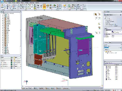
In the latest releases, KeyCreator began shedding some of its legacy interface elements, which relied heavily on menu choices. The addition of DynaHandle and previews makes push-pull editing much more intuitive in modifying patterned features, adjusting bosses and ribs, and assembly configuration.
A Different Kind of Coupling
ANSYS, like many high-end FEA programs, offers code coupling, defined as the use of more than one solver to simulate a scenario involving materials and mechanics with different physical properties and behaviors. But a different kind of coupling took place when the analysis software developer struck a partnership with SpaceClaim in 2009. The pairing gave birth to ANSYS SpaceClaim Direct Modeler (ANSYS SCDM), a version of SpaceClaim customized to work with ANSYS DesignModeler, part of ANSYS Workbench.
The bidirectional association between ANSYS SCDM and DesignModeler ensures that the edits you make in one is reflected in the other environment with a simple update. DesignModeler lets you easily defeature (remove unnecessary features from) CAD models.
Ideally, a simulation expert would like to try out different design iterations—the same design with different material thickness, for example—to discover the best configuration that can withstand the load or stress anticipated. The ability to rely on ANSYS DesignModeler and ANSYS SCDM to keep models synchronized during different iterations goes a long way in avoiding the need to export the model back to the modeling software to make changes for each analysis session.
Among PTC’s Creo app lineup is Creo Elements/Direct Finite Element Analysis. It’s offered as a plug-in to PTC’s direct modeling software (Creo Elements/Direct, formerly CoCreate) with FEA features. The bundle lets you conduct standard analyses, such as linear static, modal, buckling and steady-state thermal analysis. In addition, it incorporates stress, strain, deformation and temperature distribution throughout your product design, with combined thermal and structural analysis.
FEA Early and Often
Last fall, IronCAD, LLC and NEi Software released NEi Nastran for IronCAD, an FEA solution designed to run inside the IronCAD Design Collaboration suite products IRONCAD and INOVATE. (The capitalization differentiates the products from the company name and the name of the product suite). The suite includes products designed to provide collaboration between 2D and 3D, allowing users to leverage 3D within a 2D design process.
According to the companies’ press release at the time, NEi Nastran for IronCAD allows product design teams to perform FEA pre-processing, analysis and post-processing within the same associative design environment.
“Integrating simulation early and throughout the design process is the wave of the future for design engineers,” stated Philip Potasiak, president of NEi Software at the time of the release. “NEi Software and IronCAD have partnered to develop NEi Nastran for IronCAD to address this critical need.”
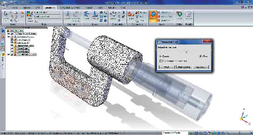
Siemens PLM Software’s Solid Edge with Synchronous Technology comes with basic linear stress analysis, as shown here. You may also use it to easily remove unnecessary details in imported 3D designs before submitting them to FEA software.
The FEA solution allows IronCAD software users to run linear static and steady-state heat transfer, normal modes, buckling, composites, and prestress; advanced dynamics like transient response and frequency response; nonlinear analysis and nonlinear transient heat transfer.
Independent Direct Modelers
Other direct modelers in the market—most notably, Siemens PLM Software’s Solid Edge with Synchronous Technology and Autodesk’s Inventor Fusion—currently have no formal integration with analysis and simulation software packages, but they still serve as better alternatives to history-based CAD programs in dealing with imported 3D designs that need to be submitted to analysis programs.
In its acquisition of Blue Ridge Numerics, Autodesk got what it needed to launch its very own CFD package. Autodesk Simulation CFD, released in August 2011, contains a license of Autodesk Inventor Fusion, the company’s direct-editing software. Siemens PLM Software’ Solid Edge with Synchronous Technology contains a set of tools for conducting basic, linear stress analysis on models. While the integrated analysis tools may not be sufficient for those seeking CFD, thermal and other, higher-end analysis tools, they are more than adequate for designers looking to validate their concepts or visualize how certain loads and pressures might affect their designs. Beside its short learning curve, the software’s comprehensive support of neutral and native 3D file formats makes Solid Edge with Synchronous Technology ideal for those who need a 3D editor for analysis models.
Accidental Discovery
Direct modelers were initially developed to ease the pain in using history-based modelers for concept exploration. The very nature of exploration demands a tool that lets you digitally build, modify and rebuild design concepts with speed and agility—something for which history-based CAD packages aren’t known. Addressing the needs of analysis and simulation experts was a market direct modeling vendors stumbled upon.
But now that they have discovered a new territory to conquer, existing and new direct modeling vendors may look at perfecting their technology to tailor it to the analysis and simulation market. They may, for instance, begin offering tools you can use to automatically detect and remove holes, bosses and rounded corners below a certain threshold. If the first batch of direct-FEA marriages prove successful, expect FEA programs to offer basic direct-modeling functions as standard features in upcoming releases.
Kenneth Wong is Desktop Engineering’s resident blogger and senior editor. He is convinced future CAD software will incorporate both history-based and direct-modeling functions. If you disagree, email him at [email protected], or share your thoughts on deskeng.com/facebook.
MORE INFO
Subscribe to our FREE magazine, FREE email newsletters or both!
About the Author
Kenneth Wong is Digital Engineering’s resident blogger and senior editor. Email him at [email protected] or share your thoughts on this article at digitaleng.news/facebook.
Follow DE

