

May 1, 2012
By Kenneth Wong
Editor’s note: Read part 1 of this article here. To read all of the articles in DE‘s recent series on direct modeling, click here.
In the past, over-engineering was an accepted way to cope with uncertainty. Today, design optimization has replaced over-engineering as the recommended approach to dealing with uncertainty. Two recent trends—the integration of direct editing into history-based CAD modelers, and the marriage of sophisticated finite element analysis (FEA) software and design software—are poised to drive design optimization even further upstream. Parametric, or history-based modeling, is favored by those trained in classic CAD programs. Direct modeling is favored by FEA experts who must adjust and refine the design, but don’t necessarily have the expertise required to dissect and understand the feature history of a design.
CAD-integrated simulation tools have also become more sophisticated. In higher-end design programs like NX and CATIA, users have the option to invoke analysis tools for heat transfer, fluid flow, air flow and other scenarios beyond simple stress and load analysis. The couplings in both fronts—the merger of history-based modeling and direct modeling, and the merger of CAD and FEA—are opening new possibilities in design optimization.
 |  |
An Overlooked, Familiar Name
It’s quite possible that someone shopping for a direct modeler might inadvertently overlook IronCAD, simply because the company hasn’t made a great effort to pitch the software as such. But for the push-pull operations possible in IronCAD, and for the software’s accommodation of both history-based modeling and history-free methods, it belongs in the hybrid modeler family.
In a memo to the IronCAD user community, IronCAD Vice President of Product Marketing Cary O’Connor wrote, “Going back to the inception of IronCAD, the goal was to make both modeling paradigms available to the user without the overhead of trying to figure out which is right for a particular task and what portions of the feature are what.”
Many direct modeling operations rely on the CAD software’s underlying kernel to resolve geometry conflicts when you push and pull on faces, or create complex fillets and shells. IronCAD relies on two kernels—ACIS and Parasolid—to perform conflict resolution in its geometry.
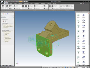
The software accommodates working in traditional history-based methods, but it also offers what it describes as direct face modification (DFM) to let you move faces by dragging and dropping. DFM operations let you break history dependency, effectively throwing you in the direct-modeling environment.
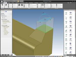
IronCAD uses a TriBall with dynamic handles to let you push, pull and reposition geometry (and handle other aspects such as images and animations). The handle may also be used to easily create duplicate copies of solid geometry and position them in 3D space.
With the dynamic handle, you don’t need to insert a construction plane to place the new geometry, or refer to other geometry for positioning. IronCAD also allows the copies to be independently edited and moved. The software’s SmartSnap function identifies snap-worthy locations—such as midpoints of edges and center points of radiuses—to let you place and refer to features with precision when dragging and dropping.
Nastran for IronCAD
Recently, IronCAD struck a partnership with CAE vendor NEi. The outcome is NEi Nastran for IronCAD, a FEA program that runs inside IronCAD software. The free version of Nastran for IronCAD limits your models to 10,000 nodes. To analyze mesh models with a greater number of nodes, you’ll need to purchase a license.
From within IronCAD’s modeling window, you’ll be able to mesh your model, add constraints, add loads, define materials, and solve the analysis scenario. The results can be displayed as contour maps, displacement maps and animation files. Integration with IronCAD’s modeling tools allows you to edit the model in the same environment where you ran your analysis, with the mesh on or off. A modified version of your design can be resubmitted to Nastran for updated results.
LiveShape Reshaped CATIA
Dassault Systemes’ direct modeling technology, dubbed Live Shape, made its debut in CATIA V6. Customers got their first glimpse of it during Dassault Systemes’ European Customer Conference 2008 in Paris. Its Group Creation function lets you select a feature and a series of related surfaces (perhaps nearby blends and extrusions) to create a group, then move the grouped faces and features to a new location by dragging and dropping.
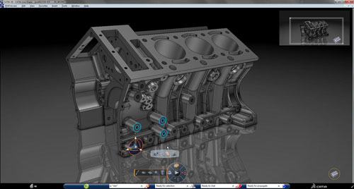
CATIA LiveShape, introduced in V6, offers direct modeling functions through push-pull operations, executable on groups of geometry.
CATIA’s Live Shape also lets you add relationships between groups (for example, a coincidence constraint between two geometry groups). With such a constraint, when you move one group of geometry, the related group follows to retain the constraint specified.
CATIA Live Shape, according to Dassault, is a direct-editing modeler which enables hybrid modeling such as solid, surface or wireframe modeling. Jacque Leveille, Dassault’s vice president of product marketing for the CATIA product line, said direct modeling is expected to offer greater flexibility in “3D conceptual design phase, 3D collaboration, downstream use, especially analysis, and ]editing] imported geometry.”
SIMULIA, Dassault Systemes’ portfolio of simulation solutions, can be integrated with CATIA V5 and works on the same platform than CATIA in V6. These integrated solutions, according to the company, “eliminate the transfer and translation of geometry and allow users to perform analysis directly on their reference model in CATIA.”
Tim Webb, SIMULIA’s director of marketing communications and programs, notes that the integrated simulation solutions that work with CATIA LiveShape also include ExSight for simulation specialists and DesignSight for those without extensive FEA experience. They “leverage the full feature-based and direct modeling capabilities of CATIA, while eliminating the transfer of geometry between CAD and FEA packages.”
Design and Analysis in Synchronicity
In earlier incarnations of Siemens PLM Software’s Synchronous Technology (ST), the difference between NX with ST, the company’s high-end CAD/CAE/CAM solution, and Solid Edge with ST, the company’s midrange CAD software, is much more apparent.
Earlier versions of Solid Edge with ST required users to fully commit to a history-free mode. By contrast, NX with ST gave users the option to work in a hybrid environment. The difference, however, may be getting slimmer as SE with ST begins to incorporate the hybrid modeling mode, beginning in SE with ST3. For those who rely heavily on simulation and analysis, NX CAE—a version of NX delivered with integrated simulation tools—is available.
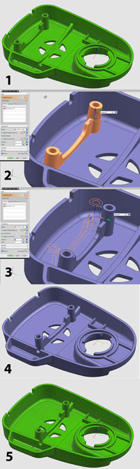 |
| With tight integration between modeling and analysis tools in NX CAE, the changes you make in your initial design are automatically reflected in the mesh model you use for analysis. |
“NX is one of the leading applications that integrate high-end simulation with direct geometry modeling,” says Ravi Shankar, Siemens PLM Software’s director of simulation product marketing. “When ST was first introduced ]about five years ago], people thought this would be great for design. I think people didn’t realize the potential for CAE engineers.”
With NX CAE, the design model and the simulation remain associative; any changes made to the design model will automatically prompt an update to the CAE model and results.
“NX CAE users can import geometry from another CAD system, modify it using Synchronous Technology, capture the changes as parameters, and use that information to drive design optimization—all this without leaving the NX environment,” says Shankar.
iPhone Convergence Lessons
A little more than a decade ago, cameras, BlackBerries and cell phones were distinctly different devices. Each performed a specialized communication function.
The genius of the iPhone was the elegance with which it consolidated these operations into a single device.
Similarly, when several subsets of design engineering are consolidated, we benefit from the ability to take our digital assets from conceptual phase to analysis, then back to CAD without shuttling the data back and forth among several different software programs, without the risk of data loss and corruption.
It’s only a matter of time before direct editing becomes a standard toolset of mechanical modelers. Five years from now, few CAD users will be asking whether a software program is a direct modeler or a parametric modeler, just as nobody today asks whether your cell phone can also send and receive texts or take photos. And it’s only a matter of time before design optimization becomes part of every phase of design, not just the quality control phase or the post-production certification phase. Nobody will ask whether your design has been optimized, because, with the toolsets you have at your disposal, everyone will expect it to be.
Kenneth Wong is Desktop Engineering’s resident blogger and senior editor. Email him at [email protected] or visit deskeng.com/facebook.
MORE INFO
Dassault Systemes
IronCAD
NEi
Siemens PLM Software
Spatial Corp.
Subscribe to our FREE magazine, FREE email newsletters or both!
About the Author
Kenneth Wong is Digital Engineering’s resident blogger and senior editor. Email him at [email protected] or share your thoughts on this article at digitaleng.news/facebook.
Follow DE

