
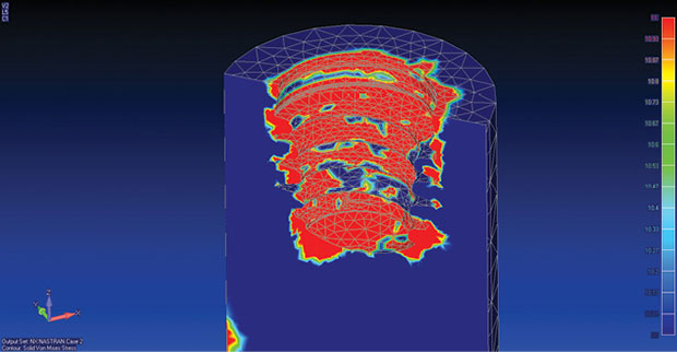
This finite element model shows stress distribution on the internally threaded half-section of a dental implant, due to mating with an abutment insert. Analysis performed with Siemens Femap and NX Nastran software. Image courtesy of Siemens PLM Software.


Latest News
May 1, 2015
 This finite element model shows stress distribution on the internally threaded half-section of a dental implant, due to mating with an abutment insert. Analysis performed with Siemens Femap and NX Nastran software. Image courtesy of Siemens PLM Software.
Did you brush your teeth this morning? Watch a sunset last night? Get a blood test a few weeks ago? Your ability to perform these everyday activities just may reflect the increasing ability of engineers to analyze the medical world, whether oriented toward human or mechanical systems. Good dental health, the best possible vision, accurate laboratory tests and more owe much to products developed through simulation software.
Both mechanical finite element (FE) and computational fluid dynamics (CFD) analysis packages offer a digital grasp of complex medically oriented systems, supporting ever more accurate functional analyses.
Implant Hardware: Refined
If your teeth brushing isn’t quite up to par, you may find yourself exceedingly grateful that companies such as Biotec btk apply mechanical simulation software to their design workflow. In 2010, the company, based in Vicenza Italy, started using Siemens PLM Software products to move from 2D into 3D CAD and incorporate FEA in its design of dental implants. Now they can’t imagine working without it.
A complete dental implant includes three sections: a threaded, machined titanium pin that goes into the jaw bone, a titanium or zirconium abutment that screws into the implant, and a custom porcelain-covered “tooth” (a coping and pin assembly that is screwed or cemented into the abutment). Biotec btk’s move to Siemens Solid Edge 3D design software allowed them to readily identify matching and interference issues when sizing the small components (implants are generally 8mm to 18mm long).
Tapping additional benefits of digital design, Biotec btk started using Siemen’s Femap FEA software to analyze stress and load distributions on the mechanical implant sections as well as on the jawbone. Stress occurs both when the abutment is screwed inside the implant, and during the chewing process. “Performing an analysis is mandatory, unless you are willing to spend a long time on mechanical tests, which would be difficult due to the tiny dimensions of our products,” says Marco Zotto, Research and Development manager at Biotec btk.
Now, being able to simulate many possible design variations also lets Biotec btk engineers address design projects they might otherwise have dismissed as impossible. “Recently, we faced the challenge of having to make an ultra-short implant. Femap played an essential role as short implants don’t seem to offer adequate load distribution at first sight,” says Andrea Peloso, managing director at Biotec btk. Simulation of a new design predicted acceptable load distribution even on a 5mm part with few outer threads. Physical testing confirmed the predicted behavior, and the implant is now sold as their Nano model; the short height can eliminate the need for bone grafts in patients with eroded jaw structures.
As the population ages, another increasingly common implant procedure is a hip replacement. The patient receives a combination of femoral stem, femoral head, plastic liner and hip-socket insert (acetabular cup). The femoral stem, typically cast in titanium four at a time, must withstand the equivalent of more than 1 million cyclic loads per year of use, so its structural integrity is critical.
Investment casting such units requires setting the optimum temperature for both the molten metal and the pre-heated casting form, along with determining the best four-part filling geometry and sequence. Otherwise, uneven shrinkage during cooling can cause unacceptable voids and surface finish in the end product. The classic approach to identifying these parameters has been by trial-and-error via building numerous wax patterns and molds; the new way is through simulation.
Inegi, the R&D engineering and technology transfer group at the University of Porto, Portugal, has elected to use FE-based ProCAST software from ESI Group for its analysis work in this area. With the assistance of the Análisis y Simulación consulting company in Spain, Inegi first used ProCast’s thermodynamic database to gather the high temperature properties of the Ti6Al4V alloy, then worked with the software to examine different approaches to the gating (filling) geometry and flow sequence. The results gave the group insight into the temperature gradients in various sections of the mold and the fill, and predicted the best combination to minimize shrinkage porosity.
Based on this information, the group designed a different gating system and a new external heater that wraps in a spiral around the outside of each femoral-insert mold, evenly distributing heat as the casting solidifies. X-rays of the finished product validated the porosity-free prostheses achieved through the improved manufacturing design.
Diagnostic Devices: Improved
Of the millions of blood tests performed daily, in both commercial and research laboratories, one of the most common is a complete blood count (CBC). Automated hematology equipment uses various technical approaches to analyze red cells, white cells and platelets, often processing more than 60 patient samples per hour. While laser-based optics perform cell sub-type identification, electrical impedance data is used to provide information about cell counts and individual sizes, the latter being on the order of 10 microns across or smaller.
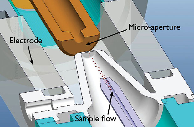 A micro-aperture section of a hematology analyzer from HORIBA Medical, showing individual blood cells (particles) streaming between sensing electrodes and the correspondence between particle size and voltage pulse determined by the changing impedance of the electric field. Image courtesy of COMSOL.
HORIBA Medical, a division of HORIBA Ltd., Japan, markets a line of hematology and clinical chemistry instrumentation and is constantly working to improve the capabilities of its products. The CBC task generally relies on a process where the blood sample is mixed with an electrically conductive reagent, pumped through a narrow channel and passed through a gap between opposing electrodes. Changing impedance properties of particles in the flow induce voltage changes proportional to the size and number of particles.
The instrument’s complex physics interactions involve high fluid velocity, heat transfer, electric fields and pressure drop through the several-microns size gap. “We use COMSOL to develop a better understanding of how these physics interact. The simulation software automatically creates the fluid domain directly from the CAD model,” says Damien Isèbe, scientific computing engineer at HORIBA Medical. One of the factors he investigated is the path taken by a cell as each traverses the tiny gap (micro-aperture) exposed to the electromagnetic field. If the cell’s trajectory takes it near the gap’s edges, instead of through the center, edge effects distort the field and result in overestimations.
Isèbe used COMSOL Multiphysics simulation techniques to account for varying particle trajectories and orientations. He also developed numerical models to prove that hydrodynamic focusing, which uses sheath flow to control and direct the sample as it passes through the micro-aperture, could be used to reduce analysis error. “Using these models,” he says, “we can precisely compute the velocity field within the device and analyze the acceleration phase to determine which designs produce the most accurate results.”
Human Systems: Understood
From the human body point of view, it’s a great time to be involved in simulation. The level of detail and accuracy now possible for evaluating not only idealized but individual patient systems is amazing. Three such models are making headway for the eye, heart and skin.
If you ever took a course in anatomy, you were probably surprised by the complexity of the human eye. This highly specialized organ contains various types of tissue, pressurized fluid-filled compartments and an intricate neurovascular system. Physicians would like to better understand the effects of intraocular (IOP) and intracranial (ICP) pressures on the retina, optic nerve and ocular globe, with their corresponding impact on vision (e.g., glaucoma).
Researchers have developed various mathematical models to identify and evaluate working parameters, but tend to view just mechanical deformations, and only on portions of the eye. Adding CFD as well as fluid-structure interactions (FSI) analyses to these investigations is improving optical biomechanics understanding.
A few years ago, several scientists across the United States tackled this problem together using FLOW-3D fluid analysis software from Flow Science. The three — Edward Furlani (University at Buffalo), Anthony Nunez (Washington University in St. Louis), and Gianmarco Vizzeri (The University of Texas Medical Branch) — analyzed a 3D CAD eye model using FLOW-3D’s TruVOF (volume-of-fluid method) and integrated FSI (FE-method based) to simultaneously model tissue deformation. This combined approach showed how an increase in pressure of an incompressible fluid in the eye’s interior deforms the surrounding layers of tissue.
This simulation is particularly challenging not only due to the range in size of the eye’s structures, measured in microns to millimeters, but also the range of properties of the tissue depending on the area being analyzed. For example, Young’s modulus varies over several orders of magnitude where the optic nerve connects to the ocular globe. Preliminary results of stress and strain have recently been reviewed in more detail with the use of FlowSight, the new Flow Science post-processing package based on EnSight from CEI.
Continuing to make news is the Living Heart Project, begun in 2014 by Dassault Systèmes as a first step in offering software-based models to assist the medical device industry. The goal is to produce design-validation tools for the entire human body and a wide variety of issues, comparable to the use of simulation software for automotive product design. The initial focus is cardiovascular disease; tackling this worldwide problem could be greatly assisted with better models of the heart.
The company’s SIMULIA division began with a simplistic, proof-of-concept model of a four-chamber heart, combining tissue-modeling techniques with thermal expansion models. Encouraged by the results, SIMULIA invited engineers, scientists and biomedical experts to help create a virtual 3D replica of a fully detailed functioning heart.
Using multiple elements of Dassault Systèmes’ 3DExperience platform, including SIMULIA’s Abaqus multiphysics simulation technology, SolidWorks CAD and 3DExcite realistic rendering, developers of the complete simulation started with scanned geometry data from an actual heart. They incorporated material property and fiber-orientation information on tissue, muscles and heart valves to develop a simulation that includes coupled fluid, mechanical and electrical effects as the heart contracts and pumps blood.
By making the Living Heart Project open for collaboration, the plan is to eventually produce patient-specific models that will help with designing and validating a wide range of medical products and procedures. The project is entering its second year, with the first commercial heart model in the beta stage. More than 45 member organizations are participating in the project, each working to improve a different aspect of the heart simulation. Current applications include adding heart disease effects, validating a heart valve assist device and virtually testing insertion, placement and performance of pacemaker leads. (For the current project status, visit here.)
A third bioengineering research field where simulation is making a difference involves killing cancer cells. In a treatment called photodynamic therapy, photosensitive drugs applied directly to the area of cancer react to irradiation of a very narrow frequency visual-spectrum bandwidth. The light source, which might shine either directly onto skin or, via some type of endoscope, onto an internal organ, has to supply uniform irradiance at an acceptable efficiency. Designing such a source requires understanding both the scattering properties within the applicator device itself as well as within the tissue (which can also absorb radiation).
ASAP (advanced systems analysis program) non-sequential ray-tracing software from Breault Research Organization is well suited to this task. Continually improved for more than 20 years, the ASAP optical imaging package can handle both biological media and opto-mechanical system design. Different forms of interoperability are available with standard CAD packages such as SolidWorks, CATIA V5 and Rhinoceros, among others.
HORIBA’S Isèbe applauds the increasing use of multiphysics-based engineering software in the medical world. “Due to advancements in computational analysis and supercomputing capabilities, numerical simulation has become the third pillar of science, next to theory and experimentation,” he says.
If these results and possibilities take your breath away, fear not — pulmonary system simulation is another hot topic.
More Info
Subscribe to our FREE magazine, FREE email newsletters or both!
Latest News
About the Author
Pamela Waterman worked as Digital Engineering’s contributing editor for two decades. Contact her via .(JavaScript must be enabled to view this email address).
Follow DE

