Documenting and Viewing via 3DVia Composer
3DVia Composer enables fast creation of vectorized high-res images and interactive animations, and maintains links for automated updates.


Latest News
January 1, 2009
By Josh Mings
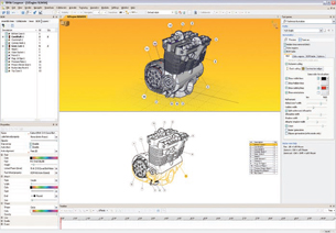 3DVia Composer allows you to quickly create exploded views and add BOM callouts to selecteditems that can be save as vectorized line art for technical publications or engineering manuals. |
A familiar request arrives. A few more screenshots of the design changes are needed to replace the old ones. This time it takes a little less time to open the model, set up the views, hope all the details are visible, and send it off one more time.
These interruptions are repeated so often, you’d think every engineer would enjoy them, but in reality, they’re extremely tedious and annoying. In a highly iterative design environment that requires product documentation, creating content to illustrate the function of a design should be simple. But keeping content up to date can turn that engineering job into an exercise of sorting and coordinating an assembly line of image-stuffed e-mails. What if there were a quicker way to create high-resolution images and interactive animations that can be updated with one click of that well-worn mouse? What if someone else could take design data as the team continues the engineering and create all of those images and animations?
Enter 3DVia Composer. It claims to add value to the 3D data produced by designers while reducing the amount of work that goes into documenting their designs. Let’s see if it can deliver.
What 3DVia Composer Can Do
3DVia Composer, a recent and unique addition to the 3D documentation scene, began as Seemage in 2002. It was acquired by Dassault Systemes in September 2007 to bring technical publication capabilities to the Dassault line of products. Shortly thereafter, it debuted at SolidWorks World 2008 as 3DVia Composer. Even though this product is owned by Dassault and is part of SolidWorks Value Added Reseller (VAR) Channel, the program can import a variety of 3D formats, including CATIA, Pro/ENGINEER, SolidWorks, Alias, Parasolid, IGES, STEP, and various image formats. It’s marketed as a tool enabling non-CAD people to take 3D CAD data and create rich deliverables — but in the hands of an engineer it becomes much more.
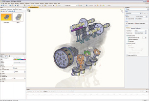 Within complicated assemblies 3DVia Composer users can hold down the tab key to quicklyghost components and select interior parts such as those indicated in color in this illustration. |
Composer is best described as a conduit between engineering CAD data and the documentation needed to create supporting information about the product design. Typically, technical publicists or marketing departments will ask for images of annotated, shaded models or drawing views, leaving the engineer to send low-resolution images via e-mail. It’s an inefficient process to say the least.
While Composer has no problem creating 2D images that can be added to documents, where it stands out is in its ability to create high-resolution vectorized images — 3D views and animations — that are linked to capture changes, even while embedded in documents or PDFs. From an engineering perspective, the content created can be used for creating paperless environments or eliminating the amount of detail drawings. Beyond that, the same images can be used in assembly instructions, maintenance manuals, training documents, and for customer service procedures.
Working in 3DVia Composer
Creating images is as simple as opening the 3D model. (Note: Some CAD formats may need to be converted to STEP or IGES.) The model is then imported and saved in an open-XML format. (This just means you can integrate it into other applications that can render XML; a truly open 3D file format.) Everything required for creating some fancy product views is brought in — assembly structure, file properties, and geometry. Unnecessary info like sketches, features, part relations, and reference geometry is left out. You select parts, create selection groups, and move around in an intuitive (middle button pans, right-click rotates) and customizable way. The display contains a hierarchical assembly tree to the left and properties for selected items directly below. It becomes very easy to select components on the screen by holding down the tab button to ghost through parts, select and change properties, and start creating views.
Views are the instances of each layout you want to capture. They’re not static either. You can cycle through them, make updates, and quickly save hi-res images. To create views you simply select the View Tab in the left pane, select Add View and go on to create more views that capture your design. There are many features available to add value. The most common ones will be Explode features, Cutaway features, and Detailed features using the Digger. These three are by far the slickest and most enjoyable features to use. All the features focus around the simple concept of click-and-drag. Although they take some fine-tuning at times, it’s quick to adjust, undo, and update views as required. High-resolution images and vectorized technical illustrations can then be saved.
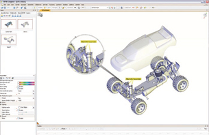 The Digger Tool can be used to create detailed views. Options to hide parts, create cross-sectionsand more are simple click-and-drag operations that make the Digger very easy to use. |
Animations can be created quickly by simply dragging different views onto the animation timeline. The view mode and animation mode can be toggled by selecting the camera icon in the upper left-hand corner of the display. More advanced properties allow prompts to be set for user interaction within the animation while other features can be used to show associative paths and simulate how parts would function in context with one another. However, when an assembly is imported, there are no inherent relationships between parts. This is important to note because if some animations require parts to move in relation to other parts, the relationships need to be created. Fortunately, the Kinematics functionality in Composer allows linking child components to parent components as well as setting limit and travel conditions for each. It basically sets limits on the part’s degrees of freedom (DOF) so they can be moved according to how the assembly was designed. If an engineer has already set these relationships up in the CAD model, they may find it very annoying to go through the process again or explain the relationship of components to that non-CAD person creating the views.
Ideally, these relationships would be brought over from the CAD program. That’s one area where even more time would be saved between the engineering and documentation effort. For animations, Composer creates an embeddable OLE player that you are able to insert into different formats, such as Word, PowerPoint, Microsoft Publisher, Adobe Acrobat, FrameMaker, or HTML documents to be used on the web.
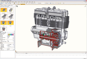 Quick cross-sections are created by selecting a point and dragging a cutting plane through theparts. Multiple Cross section and custom view properties are ideal for images that a lot of detail. |
Additional Modules
There are a number of separate modules that add functionality, but also add some confusion. 3DVia Player is a free viewer that allows people to view the 3DVia Composer .SMG files and interact with views and animations. 3DVia Safe helps you control the interaction and information available to those that view a file via 3DVia Player or any of the other exported formats. 3DVia Sync reads geometry changes and allows you to capture locations and position changes within the assembly file. Clearance Check and Path Planning are extras that allow a content creator to check assembly and dis-assembly sequences that would otherwise cause issues after parts had been manufactured. All of these together can easily triple the cost of the product. For some needing extra security or dealing with multiple design iterations, 3DVia Safe and 3DVia Sync will be must-haves. For the typical engineer, however, who needs quick views and assembly instructions to embed into a document or html page, 3DVia Composer alone will be sufficient.
3DVia Composer is, indeed, an “easy-to-use desktop content-creation system” that complements the workflow of the design process and can even be an asset to the coordination of design changes. Managing models in the relatively intuitive interface, along with a magnificent tool set for generating technical documentation, makes this an MCAD tool to be desired.
For many, it will come down to what you can do in Composer that you can’t do in an MCAD program. You can get detailed close-ups, exploded views, and cutaways out of most. You can even save views and create configurations that display parts as they would be assembled. What Composer allows you to do beyond that is quickly create those views. It makes exploded views a click-and-drag process and allows you to peel away layers of an assembly faster than tediously hiding parts. Composer then goes one step further. It throws you into an environment where you can save each view with collaborative annotations in vectorized high-res or interactive animated format and it maintains an associative link to the original MCAD model and uses the link to update views whereever they are used.
Perhaps the ideal program would be one that allows you to seamlessly, within one program, create a 3D model, animate an annotated assembly sequence with some nicely rendered views, and embed that into different formats while maintaining an associative link with the model. While that tool doesn’t yet exist, 3DVia Composer is one step closer and helps engineers do a better job in product collaboration.More Info:
Dassault Systemes
Paris, France
Please contact your reseller for the latestpricing.
Josh Mings is a technology writer based in Tulsa, OK. Send comments about this article to [email protected].
Subscribe to our FREE magazine, FREE email newsletters or both!
Latest News
About the Author
DE’s editors contribute news and new product announcements to Digital Engineering.
Press releases may be sent to them via [email protected].


