

Latest News
April 1, 2011
By Byron Blackmore
Computational fluid dynamic (CFD) techniques have been successfully applied to the realm of electronics cooling applications for about 20 years. Despite the powerful advances in solver techniques, parallelization, computer hardware, and ECAD and MCAD interfacing, CFD can still provide only snapshots of the thermal performance in a product. Usually this comes in the form of pictures or animations that display what the temperature field looks like at various locations in the model. This is useful information, of course, because it allows thermal engineers to confirm thermal compliance without building numerous expensive prototypes. Yet the question of what to do next still remains.
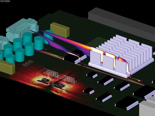 Figure 1: Bottleneck and Shortcut number distributions for a typical electronics printed circuit board. | 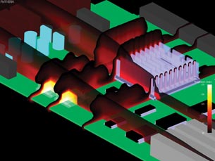 Figure 2: Temperature contour planes that intersect the TO devices and heat sink. Temperatures below 50°C have been hidden for clarity. |
Case in Point
Let’s say the initial thermal design for a product is put through a thermal simulation tool. The results demonstrate that several components are running too hot. All you really get from the temperature field in this case is an indication that you have a problem. The questions of how and why the design is failing remain unanswered, and it falls to the experience and intuition of the thermal engineer to invent a solution that will satisfactorily cool the product. This nearly always involves creating additional computational “what-if” scenarios and parametric simulations to locate a working solution, and—deadline permitting—the optimal design.
Simulating all possible design choices and selecting the best result is a proven technique, but it has two basic shortcomings:
- The additional simulations required can number in the hundreds.
- Thermal expertise is required to both avoid pursuing thermal design alternatives that have no chance of success, and to identify reasonable design limits for the parametric design space.
The state-of-the-art process for determining thermal design changes has been improved recently with the introduction of a means to visualize on screen two thermal post-processing aids: the “Bottleneck” and the “Shortcut” numbers. These two aids represent a step beyond simply observing the temperatures of a design, allowing an engineer for the first time to fully understand why a component within a product becomes hot, and how to go about fixing it efficiently. It’s the on-screen indication of “why” and “how” that’s important here, establishing a systematic means to troubleshoot thermal issues efficiently and reliably.
To understand why that is so, let’s look at what the Bottleneck and Shortcut numbers are really showing us.
The Bottleneck Number
How easily the heat passes from the various sources to the ambient will determine the temperature rise at the sources and all points in between. The heat flow paths in an electronics product are many and complex, each one carrying portions of the heat with varying degrees of ease. Paths that carry a lot of heat and impede that heat flow significantly are thermal “bottlenecks.”
Relieving the bottlenecks through a redesign would allow the heat to pass to the ambient more easily, thereby reducing temperature rises along the heat flow path all the way back to the source. Identifying the location and strength of these bottlenecks provides insight into the how and why of observed temperature behavior, and consequently can be used to guide thermal design decisions.
Typical methods used to relieve identified thermal bottlenecks in an electronics product include:
- Using a more thermally conductive material or adding copper pads or fills to sections of a printed circuit board (PCB).
- Increasing the cross-sectional area of a conduction path, such as by widening a heat sink base or fin.
The Shortcut Number
As a twist on the Bottleneck number, one can imagine that instead of relieving a thermal bottleneck, one might simply go around it by creating a new conduction path. The best areas in a design to build a new conduction path are called thermal Shortcut opportunities.
A large Shortcut number will appear when the heat flow is moving in the wrong direction. “Wrong,” in this case, means it is not moving in a straight line toward the ambient (or locally cooler) area of the design. Like the Bottleneck number, the Shortcut number offers insight into how and where the thermal design can be improved.
So far, the Bottleneck and Shortcut parameters have been framed in the context of conduction within solid objects. But the Shortcut number has implications at a convective surface as well. The underlying mathematics of the Shortcut number provide a correlation with local Nusselt numbers—that is, both will have large values where convection heat transfer is efficient.
Evaluating a local Nusselt number outside of simplistic geometric and fluid conditions can be cumbersome. Thus, using the Shortcut-Nusselt number correlation is an efficient means to identify and visualize effective convective surfaces, offering additional insights into thermal design performance.
A Design Change Strategy
The general strategy is to perform a simulation and inspect both Bottleneck and Shortcut fields to determine which areas of the design should be prioritized when considering thermal design changes. Armed with information about Bottleneck and Shortcut opportunity locations, targeted design changes can be developed. The exact details of the changes will be determined by other design constraints (electrical, mechanical, cost) and how evolved the complete design is.
Generally speaking, Shortcut-inferred design changes should be considered first, as the creation of a new heat transfer path can completely change the heat flow topology for a design, and cause pre-change bottlenecks to greatly diminish in importance. After all, the new conduction path may bypass previously existing bottlenecks.
In Figure 1, we have the thermal simulation results for a PCB being cooled by forced convection. There are two types of information on display here:
1. The pair of TO-263s (shown in wireframe) is displaying heat flow lines that emanate from the die. These heat flow lines are colored by the Bottleneck number. In this case, the white color indicates a near-maximum level bottleneck, and black means a small Bottleneck number. The strongest bottlenecks for these components occur where the heat begins to enter the PCB from the copper spreaders. This area should be addressed first when considering a design change to reduce the TO-263 junction temperatures. As mentioned earlier, one possible way to relieve a thermal bottleneck is to introduce locally a material with a larger thermal conductivity. In this context, introducing a copper fill area to the PCB would be an excellent design change.
2. There is a contour plane showing the Shortcut number positioned such that it is near one line of heat sink fins. Again, we’re using white to represent larger Shortcut values, and black to represent small values, although the color range differs from that of the Bottleneck scale. As the Shortcut number corresponds well to the Nusselt number, we can see that the top portion of the leading fin is not as efficient at moving heat into the airstream as the ones behind it. If the design were under pressure to reduce cost, removing this section of the heat sink would be a reasonable place to start, as we would be reducing material costs in a location where the thermal performance hit will be minimized.
At this point, the designer would introduce either of the changes above and redo the simulation. The updated results would have a new set of bottleneck and shortcut targeted areas, from which a second design change can be derived.
Now let’s compare the design work flow for the case where we have only temperature results to guide us, as shown in Figure 2. For the TO-263 devices, the practitioner would, by comparing the observed junction temperature values to the maximum rated values, recognize that a thermal problem exists. The workflow from this point involves drawing on the experience of the engineer to determine a course of action. This might include heat sink design or adding thermal vias, larger spreaders or copper fills, each of which will involve many additional what-if scenarios or parametric investigations.
Using the Bottleneck and Shortcut fields together provides valuable design insight as to why the temperature distribution for an electronics system is what it is. Application and interpretation of these post-processing parameters offers a methodology for determining the most promising thermal design improvements, without necessarily relying on thermal experience and intuition.
This is an important gain in simulation productivity: Rather than simulating potentially hundreds of thermal remedial actions and choosing the best one, engineers can now pinpoint on-screen where the best design changes are most likely to be found—and start designing.
More Info:
Mentor Graphics Corp.
Blackmore is electronics cooling product manager for Mentor Graphics Corp. Send e-mail about this article to [email protected].
Subscribe to our FREE magazine, FREE email newsletters or both!
Latest News
About the Author
DE’s editors contribute news and new product announcements to Digital Engineering.
Press releases may be sent to them via [email protected].


