

December 1, 2012
By Vince Adams
In the first years of the last century, Thomas Edison optimistically commented on his numerous prototypes for an electric storage battery: “Well, at least we know 8,000 things that don’t work.” Contemporary estimates put the actual number of prototypes around 50,000 over a 9-year period.
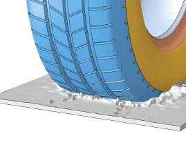 |
| Multiphysics solution of a tire splash.Image courtesy of Dassault Systemes SIMULIA. |
More recently, James Dyson advertised that he built more than 5,000 failed prototypes before perfecting his dual cyclone bagless vacuum cleaner. Try to imagine the look on your manager’s face if your project plans included that many prototypes. Unless your name was on the building, it probably wouldn’t have gone over well.
However, engineers know the more iterations they can try in the time permitted, the faster they’ll get to an acceptable design—and the more likely they’ll approach an optimized design. It is this challenge that drove the pioneers of industrial finite element analysis (FEA), and the first practitioners to the craft. It remains the vision today.
To fully appreciate the value of FEA-based optimization to your organization, some understanding of how today’s technology got to where it is and how it can best affect the design process is warranted.
FEA: Then and Now
Pioneers in structural mechanics, such as Stephen Timoshenko, Walther Ritz and Lord Rayleigh, paved the way for a breakthrough in predictive stress/strain by Richard Courant in 1943. Courant proposed the concept of triangular segments as a basis shape for more complex structures. He leveraged the research of those who came before him to interrogate possibilities and find the deformed structure with minimal distributed energy. The birth and growth of computing in the 1940s and 1950s allowed application of this basic concept to real-world problems in the aerospace industry.
Commercial FEA, along with the name “Finite Element,” was born in the 1960s with the development of ANSYS, MSC/NASTRAN and MARC. It was still a specialist technology, employed primarily in the automotive, aerospace, defense and nuclear industries. Shared computing centers were often required to get manageable throughput. But by the 1980s, CAD put computers in the hands of engineers in all industries—and access to FEA followed shortly.
The early design analysts were challenged with model size limitations of a few thousand nodes. They were challenged to make every element count, thanks to the manual methods of node/element creation and the compute power ceilings.
In the 1990s, solid modeling for CAD took hold for good, and CAD-based meshing evolved with the rapidly increasing power of desktop computers. The geometry-centric workflows we now take for granted started to take shape. The potential for design analysis and optimization became a reality. In 1994, Altair’s OptiStruct topology optimization ushered in a new way of leveraging FEA by allowing engineers to explore possibly counterintuitive geometries by specifying loads, failure conditions and the allowable design space or physical envelope a part can occupy.
Growth of FEA in Product Design
To truly understand the role of simulation in the design process, let’s first take a step back and examine the process itself.
The design process is not a linear process. It often wanders through a sequence of decisions and adjustments. A misstep that isn’t caught fast enough can throw the project down an unproductive path. Periodic affirmation that the design is on the right track, much like GPS in your car, can help avoid costly detours.
Calculations, prototypes and analysis provide this guidance to engineers. Because too few real-world geometries can be simplified to hand calculations, they have limited value. Similarly, the very nature of most physical prototypes require that many, if not most, design decisions be made prior to fabrication. The end result is usually an expensive guess that, if deemed sufficient, will rarely be optimized. Fast, affordable FEA can bridge the gap between simplistic hand-calcs and expensive physical prototypes, while offering a vehicle to rapid exploration of variations and improvements.
CAD integration was the catalyst for making FEA a “virtual prototype” tool. Design integrated analysis allows us to explore more prototypes in significantly less time, even if they are simply minor variations. The net result is that we can linearize the design process so that explorations of variants never stray too far from the right path.
Even without detailed loading, material properties or failure criteria, choices can be examined for being overly conservative, dangerously marginal or worth evaluating further. Each feature, parameter or decision can then be optimized on the fly, so the chances of the first acceptable design being closer to the optimal one are greatly increased. Five thousand to 8,000 prototypes, virtual prototypes, aren’t unrealistic in this scenario.
Impact Still Small
With all this potential, why is the use of FEA still limited to a small percentage of engineers at most companies? In a presentation offered at the 2008 NAFEMS Regional Summit in Hampton, VA, Dr. Dennis Nagy, a longtime FE industry expert, estimated that companies were only using 10% to 15% of “already purchased CAE capability.” He said he believes these companies can realize increased value from deeper and improved utilization of existing CAE without any further investment.
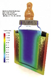 |
| Temperature distribution in a baby bottle, presented with photorealistic CAD in SolidWorks Simulation.Image courtesy of Dassault Syst mes SolidWorks. |
The reasons for this underutilization are certainly more cultural than technological. A leading factor is that too few managers have mandated or allowed a process change that leverages simulation. FEA can’t drive a design if it is only used to validate finished concepts. Furthermore, without a process change, it is likely that the design being validated digitally is the one that would have been validated physically. Awareness of this fact artificially devalues the simulation process.
At the user level, designers still haven’t learned to properly phrase their questions to a simulation. “Will it work?” isn’t specific enough for today’s FEA. Unfortunately, engineers new to this flood of detail about a design aren’t prepared to recognize what the results are telling them—either about the design or the quality of the simulation. More training on input properties and failure mechanisms will allow them to make more decisions and delve deeper into an optimal configuration. A doctorate in applied mechanics isn’t required—but a working knowledge of the materials being specified, and the applicable failure modes of a product are necessary.
The tools an engineer needs are probably available on his or her PC today. Learning how they apply to the decision-making process should be the first priority before looking to add new or deeper levels of simulation.
FEA Trends
One sure sign of a maturing technology is that the trends today sound much like the trends of 5 years ago. That isn’t to minimize the importance of the development work being done in the industry. The growth plan for design analysis is significant and potentially game-changing. In the end, it may turn into a race to see who completes it first.
A look at top FEA developers shows three general areas of focus:
1. Add more realism to the analysis. At its heart, an FEA solver is truly a general-purpose calculator. Triangles and nodes respond to forces and constraints. The solver doesn’t know if it is simulating a child’s toy or a wind turbine. This puts the responsibility on the user for making sure the mesh, properties, loads and restraints act like the product under study. They must also interpret the results in light of what that product might actually do. To grow the value of simulation to generalist engineers, software developers are attempting to break down long-standing barriers so that simulation truly feels more like design.
Examples of this include multiphysics (MP) and multi-domain simulation. Instead of sequentially solving a deformation scenario, then a fluids scenario—traditionally different governing physics—engineers are beginning to see coupled fluid-structure interaction shifting to the mainstream. Other MP applications include simultaneous solving of thermal, electro-magnetic, acoustic, fluids and other phenomena with structural responses, much like a product or system would experience in real operation. We can expect this to be refined over several more years, since gains in computing speed need to match improvements in user interface and solving algorithms to truly deliver on the promise.
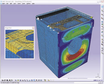 |
| Sound radiating from a clothes dryer. Image courtesy of LMS International. |
Whereas MP solutions typically compute multiple responses in the same or similar mesh space, multi-domain simulation simultaneously links varied technologies to create a true virtual product. The most common and mature example of this is flexible, strain computing bodies in an otherwise rigid multi-body dynamics (MBD) analysis. Highly transient 1D hydraulic, pneumatic and mechatronic systems are now being coupled to MBD and computational fluid dynamics (CFD) solvers.
Finally, developers are growing vertical applications for disciplines such as turbo-machinery, airframes and composites, so that industry knowledge is tightly coupled with the solving application. This allows engineers to focus more on the real problem than the analysis itself.
2. Tighter integration with CAD and geometry. An interesting dynamic in the industry is that the simulation companies that started in the FEA business and those that grew from the CAD world seem to be growing toward the same vision: a blurred line between CAD and CAE. Dr. Paul Kurowski, author of numerous books and articles on design analysis and president of Design Generator Inc., sees this direction as the natural evolution of both disciplines: “Engineers with an awareness of the needs and value of simulation will make better design choices from the start.”
To this end, meshing tools are becoming more tolerant of sub-optimal geometry. They even recognize features like holes and anticipate a more appropriate mesh. Parametric geometry changes will morph an existing mesh where possible. Intelligent decisions about element type (beam, shell, solid), are being made based on an analysis of geometry without remodeling—and when required, the software can facilitate the reduction of solids to true analytical geometry. CAD-based part-part contact is considered mainstream functionality, so engineers can focus solely on assembly interactions.
The development effort in this arena will be ongoing for several more years. It is less constrained by computational efficiency as by the creativity of the software companies and the cultural acceptance of the user community. They must work together to realize the best combination of capabilities.
3. Improved speed. Speed is always on the table for FEA developers. One of the biggest factors is computer speed—which is out of the FEA developer’s control. However, making better use of both the available CPU power and the operator’s time is. To that end, we’ll continue to see improvements in solving algorithms and mesh technology that provide better results with fewer nodes. Additionally, multi-core computers and high-performance distributed solving will be leveraged for rapid turnaround of traditional and newer MP scenarios.
The speed of the total process is being addressed as well, through automation and simulation data management (SDM). Automation will allow repetitive tasks to be scripted and parameterized. This direction has been pursued for more than a decade, and has caught on in certain industries, but it’s not widespread. However, SDM is an idea whose time has come now that product data management (PDM) and product lifecycle management (PLM) have taken root. Most players in the FEA software industry have some strategy for SDM, and it may help pave the way for the real benefits of automation down the road.
Where is Optimization on this Road Map?
At first glance, a look at leading developers suggests only incremental improvements in optimization technology going into 2013. That’s not because the value of optimization has diminished, but that optimization technology is ahead of the factors needed to make it successful. These include MP/multi-domain simulation, design integration, speed and cultural acceptance.
Also remember that manually iterating (such as the work of Edison and Dyson), is still optimization—and it’s more consistent with the way designers have always worked. When the barriers being addressed by the three long-term growth trends come down, and engineering organizations begin to rely more on simulation for design excellence and competitive advantage, automated optimization will truly come of age.
Vince Adams, currently an account manager for LMS, is a longtime simulation educator, consultant and speaker. He has authored three books on FEA and numerous magazine articles. Send e-mail about this article to [email protected].
INFO
Subscribe to our FREE magazine, FREE email newsletters or both!
About the Author
DE’s editors contribute news and new product announcements to Digital Engineering.
Press releases may be sent to them via [email protected].
Related Topics


