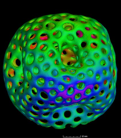
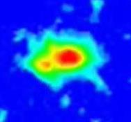
(Top) Meltpool monitoring volume image of additively manufactured metal organic sphere with a high degree of porosity and (bottom) a CT scan of the same object. The first technology predicts flaws based on real-time in-situ measurements taken during an AM build; the second examines finished products for integrity. Sintavia and Concept Laser collaborated on a study of the correlation between the two quality-assurance methodologies.


Latest News
July 31, 2017
Now that metal additive manufacturing (AM) is creating fully functional industrial parts, many OEMs are taking a closer look at how the technology might support their individual production goals. Interest has also been piqued by the commitment to AM of some very major players.
“I think the news about the GE Leap engine fuel nozzle really resonated throughout industry,” says Doug Hedges, president and COO of Sintavia LLC, a metal AM service provider for aerospace, defense and other industries. “That got everyone’s attention and certainly increased the pace of inquiries for us.” The nozzle, produced internally at GE, was the first 3D-printed part certified by the U.S. Federal Aviation Administration (FAA) to fly inside a commercial jet engine.
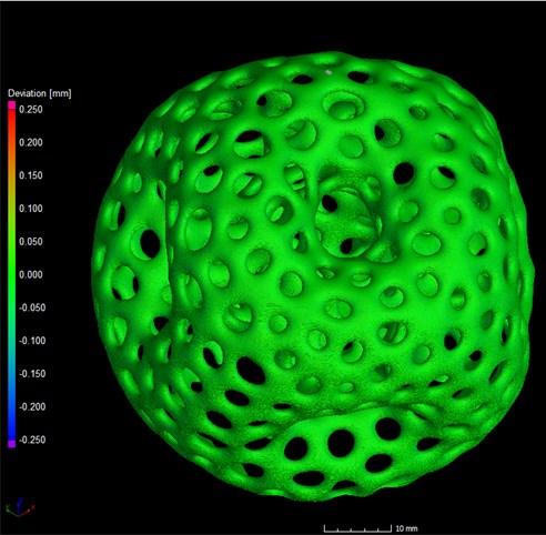 Meltpool monitoring volume image of additively manufactured metal organic sphere with a high degree of porosity (above) and (below) a CT scan of the same object. The first technology predicts flaws based on real-time in-situ measurements taken during an AM build; the second examines finished products for integrity. Sintavia and Concept Laser collaborated on a study of the correlation between the two quality-assurance methodologies.
Brian Neff, Sintavia CEO, had already founded Sintavia (a combination of “sintering” and “aviation”) in Davie, Florida in 2012, the year before the GE milestone announcement. Informed by his and Hedges mutual aerospace backgrounds, they’d had an eye on AM for quite some time.
“Additive manufacturing is a very challenging field,” says Hedges. “We felt we needed to enter it in the early stages—rather than wait until the industry was more mature—in order to refine our skills.” Their AM resources now include five machines from three of the leading metal manufacturers as well as an electron beam melting (EBM) system—and they are finalizing plans for a new facility, over five times the size of the current 10,000-square-foot building, to open in mid-2018.
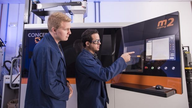 Sintavia applications engineer Shawn Morgan (left) and additive technician Juan Manjarres (right), work with one of the metal additive manufacturing company’s newest machines, an M2 cusing from Concept Laser.
Metal AM for Aerospace
While metal AM is at the center of Sintavia’s offerings, their core competencies also include full material characterization (including ISO 17025 accredited powder analysis and mechanical testing laboratories), as well as finishing processes such as Heat Treatment, HIPing (Hot Isostatic Pressing), and CNC machining—plus CT scanning to inspect the integrity of the final product. “AM gets much of the attention, but post-processing and analysis are pivotal to delivering critical parts,” says Hedges. “Our customers are looking for a facility that can control the entire AM-build process.”
After five-plus years in operation, Sintavia’s client roster is currently about 75-80% aerospace (including all of the top-20 OEMs) plus oil & natural gas, automotive, and turbomachinery for power generation. Clients are interested in AM research and development (R&D) as well as production of finished parts.
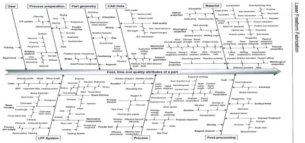 The Ishigawa diagram of process parameters for additive manufacturing.
Their aerospace customers focus on everything from aircraft to satellites to weapons, according to Hedges. “There’s flight hardware that would go on a Boeing 787 and then there’s flight hardware that might go on a satellite or an unmanned vehicle,” he says. “To qualify parts for flight hardware of any kind is a very intensive thing but for human travel the substantiation is a lot higher. So the better monitoring of manufacturing you have, the better inspection you have, the more assurance you’re going to have to say this product is capable of a flight usage.”
Many of the same materials used in aerospace are also employed by Sintavia customers from other industries, Hedges points out. “An oil and gas equipment supplier may want us to build a wellhead cap, a sensor, or a tool that needs to be extremely corrosion-resistant—so they use the same superalloys, often Inconel 625 or 718, as those in jet engines,” he says. “With steam turbines, which are basically just jet engines on the ground, the hardware undergoes much of the same stresses as a jet. So the materials used to additively manufacture all these parts are often remarkably similar.” AM can make such superalloys easier to work with, Hedges notes. “Inconel is notoriously difficult to machine, but AM allows you to create complex interior channels directly within a build, cutting down considerably on machining time.”
Mastering the Complexity of AM
As their business accelerates, Sintavia’s AM expertise continues to deepen, along with a profound understanding of the unique complexity of the technology. The “wishbone” roadmap, known in the industry as the Ishikawa diagram of process parameters for AM, continues to guide their inquiries into the many variances that could potentially affect part quality.
 Graphic of the Concept Laser QM Meltpool 3D system.
“AM has many more input parameters than traditional manufacturing and many of these factors are also more difficult to control,” says Sintavia lead engineer Pavlo Earle. Prior to joining the company he spent eight years at Rolls-Royce specializing in welding, brazing and additive manufacturing. “There are many fundamental similarities between AM and welding,” he notes. “There was an intense focus on quality at Rolls-Royce; here at Sintavia we’re equally devoted to learning, understanding, and controlling every aspect of the pre- and post-process parameters that have an effect on the quality and cost of a product.”
There is growing demand for this kind of attention to detail across industries either engaged in, or wanting to become involved with, additive manufacturing, says Hedges. “At this point in time the most pressing needs for additive manufacturing are industry standards that incorporate ASTM, AMS, implementation into the MMPDS, material and process specifications, data collection and access, post processing, fatigue assessments and standards that include actual CT scanning instead of film.
“We differentiate ourselves by helping customers develop parameters and processes that work towards establishing such industry and company standards.”
Monitoring the Meltpool
This philosophy of supporting quality production with intense R&D was behind Sintavia’s latest Direct Metal Laser Melting (DMLM) machine acquisition—a Concept Laser M2 cusing system—in the autumn of 2016. German AM provider Concept Laser is known, not only for its equipment, but also for its “QM Meltpool 3D” technology, which won the International Additive Manufacturing Award (IAMA) earlier that same year.
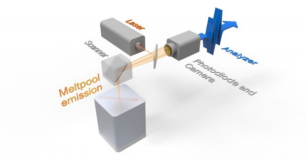
 Infrared camera image of an AM meltpool as the laser melts powdered metal.
The QM Meltpool 3D system monitors specific process parameters of a LaserCUSING (pronounced like ‘fusing’ but with a ‘c’ for “Concept’) build as it’s actually in progress. A series of semi-permeable mirrors are positioned to both steer the path of the laser (following the CAD geometry of the object being printed) and to reflect back emissions data (thermal radiation), about the meltpool in progress, to an on-axis camera and a photodiode. This setup keeps the sensors out of the actual build chamber, an important safety benefit. The combination of camera and photodiode provides much greater monitoring precision than other AM systems that use a single photodiode alone. The thermal detection data is correlated with the toolpath of the laser spot as it melts the metal. This allows for the identification of any deviations from the set requirements for laser-energy, meltpool heat intensity, powder material thickness, and so on.
The data continually runs through software that calculates the average emitted meltpool intensity and area per build layer, providing a moment-by-moment, high-resolution visual prediction of the process. Volume Graphics’ data analysis and visual analysis software then combines the input from multiple laser passes into a voxel image of the part and its internal structure. This gives the operator a continuous, three-dimensional view of the growing part and enables them to detect any potential for irregularities in the build as it progresses.
Meltpool Monitoring and CT
Shortly after acquiring their Concept Laser machine, Sintavia purchased a 5-axis Nikon CT scanner—and an opportunity arose to compare results from meltpool monitoring with CT scanning when Concept Laser approached Sintavia to offer support for a joint study on the relationship between the two technologies.
“We see Sintavia as a unique advanced manufacturer who are progressive users of metal AM,” says Concept Laser’s U.S. president and CEO John Murray. “Their specialization in aerospace applications made them even more of an ideal match for this project because they are making flight-critical parts where quality monitoring is essential.”
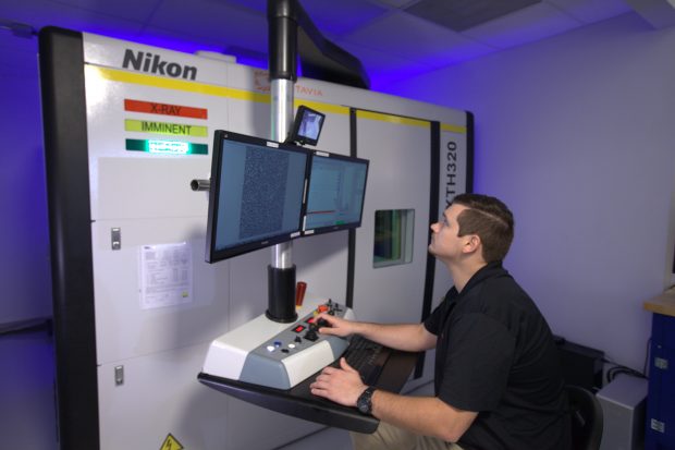 Sintavia lead engineer Pavlo Earle with the company’s CT scanner.
Sintavia in turn wanted to strengthen their quality-assurance capabilities by exploring the value of meltpool monitoring and CT in tandem, says Hedges. “CT is a natural extension of the technical expertise in metallurgy and metrology that we think is extremely important to the future of AM.” The Concept Laser M2 cusing and the Nikon CT scanner share the same software, an advantage that helps avoid any interoperability issues.
CT scanning—a valuable tool for assessing traditionally manufactured products in certain industries—is already a requirement for most critical parts, Hedges points out. “It’s a great tool that allows you to see both internal and external geometries, detect voids, confirm densities and then perform extremely high-value metrology for first-article dimensional inspection,” he says.
However, CT scanning is performed after a product is manufactured; any defects detected at that stage must be assessed as to whether they affect a part’s integrity and, if so, corrected if possible, or discarded. This costs both time and resources—and the latter can be considerable when working with superalloys.
Meltpool monitoring, on the other hand, can identify potential problems at any point during an AM build, providing the manufacturer with opportunities to halt the run and change settings or even scrap the entire setup before additional material is wasted. In terms of initial outlay, meltpool monitoring is less expensive than CT by a factor of about ten and it has no continuous operation costs once set up.
Creating Defects on Purpose
“Starting this project, the fundamental questions we wanted to answer were, ‘Is data from in-situ monitoring similar to a CT scan and, if so, can it be used to qualify parts?’” says Earle.
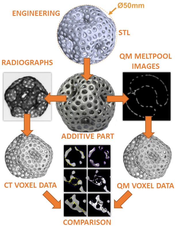 Workflow of the test of one of the shapes (organic sphere) in the Sintavia/Concept Laser project. Center top two images are the CAD design of the sphere with defects, and the finished product. Down the right side are the QM Meltpool 3D images, down the left are the CT scan results. Bottom six figures demonstrate the correlation between defects predicted, and then identified, by the two technologies.
“Long term, the goal for serial production with AM is to be able to build a reference job with active QM Meltpool 3D and then investigate finished part quality by using CT or cross sections. The QM Meltpool 3D data of the reference parts can then be compared with all further build jobs of the same design. If there are no significant incidents during the build job, there is no need for additional and expensive post-process examinations.”
As Earle and his team began setting up their trials they realized that, given the high accuracy of Concept Laser’s stock parameters with the M2 cusing machine, they would have to create artificial build errors in order to assess QM Meltpool 3D’s detection capabilities.
First they designed three different shapes to work with—an “organic” sphere based on the structure of a rocket fuel particle, a canted helix, and a series of density cylinders with artificial pores ranging in diameter from 30 µm to 2 mm. Then they deliberately created irregularities in the powder bed process due to factors such as uncalibrated scaling, overexposure, a cold pause, a too-thick recoat layer and other changes in parameters that might create build flaws—in this case focusing solely on voids. The finished shapes were then CT scanned to determine if the voids predicted by QM Meltpool3D actually occurred.
It is interesting to note that not every deviation that meltpool monitoring detects in a single AM layer will necessarily lead to a void that would cause a part to be scrapped. Subsequent powder layers melted by laser input sometimes “heal” small deviations as the process continues. In this study Sintavia considered predictions for voids that were five times the size of QM meltpool resolution (5x70µm = 350µm). “With a void of that size, we can say with a high degree of confidence that this is a location of low or high power density where there could be a void,” says Earle. “But QM Meltpool 3D can detect energy density deviations and irregularity that starts as small as 70 microns, which is the resolution of the data.”
What the final data revealed was highly significant: QM Meltpool 3D predicted the flaws that CT detected.
“We’re seeing more than just correlation, we’re seeing causality,” says Earle. He presented Sintavia’s findings at the Additive Manufacturing Users Group (AMUG) earlier this year.
“This was our first trial look at quality meltpool monitoring and these results are important,” he says. “It’s a continuing art that will take more work in order to completely understand the relationship between meltpool monitoring and CT scanning. But we are on our way to that. I definitely see a proper design of experiments (DOE) with quantitative data and a real analysis in our near future.”
Hedges agrees. “We’re at the very beginning of this comparative process but what it offers to critical parts is really, really big. When in-situ monitoring becomes mainstream, the additive manufacturing industry will accelerate.”
Subscribe to our FREE magazine, FREE email newsletters or both!
Latest News


