ESA Models Ramjet Cooling Using CFD-ACE+
Modeling with turbulent flow is key in the European Space Agency's evaluation of porous media in transpiration cooling.


October 1, 2008
By Jerry Fireman
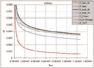 Figure 1: This graph demonstrates that the turbulent skin friction curves obtained for the adiabaticwall with Chien and k-ω turbulence models are in good agreement with the theoretical curves. |
Transpiration cooling, which uses coolant flowing through a severely heated component to carry the heat away, might be the best way to cool ramjets being developed for propulsion of hypersonic aircraft at speeds ranging from Mach 2 to 10.
The porous media used in transpiration cooling has been successfully simulated many times under laminar flow assumptions but difficulties have been encountered in simulating turbulent flow. Researchers at the European Space Agency (ESA) in Paris are testing the ability to simulate turbulence in the main flow while the laminar flow assumption is used in the porous media itself. High-performance computing capabilities are critical in modeling porous media and the ESA has used up to 48 processors in some calculations.
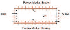 Figure 2: This is a schematic of a test case involving flow between porous plates. The channel is 2meters long and 1 cm high. The thickness of the porous media is 1mm. |
Challenges Posed by Transpiration Cooling Sims
Fuel and a combustion-supporting gas such as air or hydrogen are injected into the combustion chamber of a ramjet. When operating at speeds greater than Mach 5 or so, combustion occurs in a supersonic flow. Temperatures on the order of 3,000 degrees Kelvin are experienced in the combustion chamber. Conventional materials are not able to withstand temperatures of this magnitude and require active cooling.
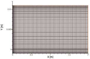 Figure 3: In this grid of the third test case, the bottom layer of the porous media is located betweeny = -0.001m and y = 0m. The top layer is located between y = 0.01m and y = 0.011m. |
These components have an inner wall consisting of a porous material with numerous apertures that are typically on the order of 100 to 300 microns in size. A gas or liquid called the transpirant passes through these pores to cool the component.
Modeling of the transpiration cooling is critical in evaluating alternative designs for hypersonic transport. But porous media presents a major simulation challenge because the pores are irregular with respect to size and shape and at the pore scale the flow quantities are also irregular.
Another challenge is that conventional computational fluid dynamics (CFD) software typically used to simulate fluid flow requires that the entire computational domain be defined as either turbulent or laminar flow. This creates a problem in modeling porous media because the small scale of porous media makes turbulent modeling impractical with today’s technology — yet turbulent modeling is essential in the main flow sector, typically the combustion chamber.
Figure 4: This is a table for the range of porous injection speed and the correspondingReynolds number. |
Three Test Cases
Francois Cheuret, fluid dynamics engineer for the ESA, used CFD-ACE+ software from ESI Group to model several different common porous media problems using turbulent flow. This software provides a porous media model as well as the ability to segment the model into different volumes that can incorporate either turbulent or laminar flow. The first test case is open flow along a porous plate with transpiration cooling. The second test case has one closed channel with symmetric cooling injection. The third test case represents a closed flow between two plates with asymmetrical injection and suction on the opposite walls. Subsonic flow was modeled in these simulations with both main and coolant flow being incompressible.
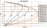
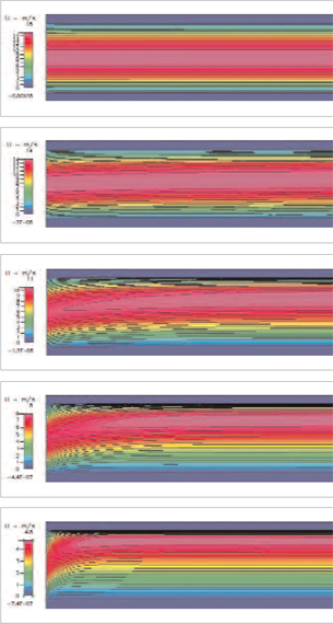 Figure 5: This sequence of visualizations describes the axial speed of the flow at various injectionspeeds. The simulation correlates with analytical solutions as shown in Figure 6. |
These simulations used the porous media model in CFD-ACE+, which makes it possible to add a porous media region simply by activating the porous media feature on any fluid volume. The user changes the volume condition setting to porous media and then specifies the porosity and permeability of the porous media region. Porous media inputs can be specified for either an isotropic or anisotropic resistance. A key advantage of this software is that along with porous media this software handles the complete multiphysics including compressible flow, conjugate heat transfer, turbulence, and chemistry.
Several turbulence models are available and they were validated prior to beginning the study of porous media using a flat plate. The domain is 2.1 meters long spanning a flat plate of 2.0 meters long and extending 0.1 meters upstream of the leading edge. The height of the domain is set at 0.1 meters. The laminar flow model and three available low-Reynolds turbulence models in CFD-ACE+, k-v, SST k-v, and Chien k-e were evaluated. Figure 1 shows that the turbulent skin friction curves obtained for the adiabatic (no transfer of heat) wall with Chien and k-v turbulence models are in good agreement with the theoretical curves. The remainder of the study was done with the k-v turbulence model.
Modeling Porous Media with Turbulence
Figure 2 shows a schematic of a test case involving flow between porous plates. The channel is 2 meters long and 1 cm high. The thickness of the porous media is 1mm. The flow close to the porous media is of critical concern because it involves the porous flow as well as friction and heat transfer at the wall, possible combustion of the cooling fluid, and the interaction of shock waves with the boundary layer. The speed vw is the velocity at the exit of the porous plate. A positive value corresponds to blowing while a negative value indicates suction. The mesh construction is shown in Figure 3. The bottom layer of the porous media is located between y = -0.001m and y = 0m. The top layer of the porous media is located between y = 0.01m and y = 0.011m.
Revw is the Reynolds number related to the porous injection speed vw and the height between the plates 2H. The range of porous injection speed and the corresponding Reynolds number are indicated in Figure 4. Figure 5 shows the axial speed of the flow for different porous injection speeds. The simulation correlates with analytical solutions as shown in Figure 6. The agreement is good for each porous injection speed. Some differences can be observed in the case Revw = 1. This can be understood by examining the second image of Figure 5, which shows that the flow is not completely established because of the low porous injection speed value.
 |
Based on this successful validation of 2D porous media simulation with turbulent flow, Cheuret of the ESA is now making plans to begin modeling more realistic 3D porous media problems. These simulations will be large problems involving millions of cells and will thus require parallel processing in order to provide results in a reasonable period of time.
“In other 3D applications, I have used up to 48 processors for problems involving up to six million nodes,” Cheuret said. The porous media model and related modules that will be involved in this work, including the flow module, heat transfer module, turbulence module, and chemistry module are all supported by parallel processing in CFD-ACE+.
More Info:
ESI Group
Paris, France
esi-group.com
Jerry Fireman is president of Structured Information, a technology consultancy in Lexington,MA. Send your comments about this article to [email protected].
Subscribe to our FREE magazine, FREE email newsletters or both!
About the Author
DE’s editors contribute news and new product announcements to Digital Engineering.
Press releases may be sent to them via [email protected].


