

Latest News
April 9, 2009
By Matt Lombard
 A history-based feature list with the resulting model from SolidWorks. |
Bold claims accompanied the release of Solid Edge with Synchronous Technology almost a year ago, and separating fact from fiction was difficult with ads and even analyst white papers using phrases like “100 times faster” and “unbounded editing flexibility.” In this article, we explore the conceptual underpinnings of the technology.
History-based Modeling
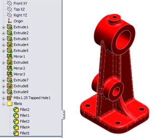
History-based modeling is often described as a recipe where you put together various features that typically use a 2D sketch to perform a process such as extrude or revolve, either adding or removing material. The software records the sketches, features, and the order in which they are applied, and it allows you to step back through the chronology and make changes (see Figure 1).
History-based models are often referred to as “intelligent” because they build into the sketches and features the parametric rules followed as the model changed. Conversely, imported models are called “dumb” geometry because they have none of this intelligence.
One weakness of history-based systems is that the features in the history tree are recalculated when the part changes, which can take a lot of time for a large number of features. Recalculation also introduces the possibility that some features will fail due to the changes.
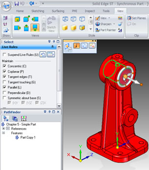 This image shows the SolidWorks part from Figure 1 after it has been imported into Solid Edge as a Synchronous Part. |
Direct Modeling: A History-based Alternative
Direct or explicit modeling is one alternative to history-based modeling. Direct modeling involves creating solid geometry through sketches, and then moving faces directly rather than moving them indirectly via sketches and features. One advantage of direct modeling is that it does not have the overhead of a process; there is no list of steps. It also does not have to rebuild at every change, thus avoiding potential failures.
Direct modelers are becoming popular because the models are easy to create and easy to change, and there is no difference between imported and native models. For this examination of Solid Edge with Synchronous Technology (ST), I went through training much like a Solid Edge reseller might receive to come up to speed on ST.
History and Direct Modeling, or History or Direct Modeling
One of the biggest questions that people seem to have about Synchronous Technology is whether you can have both history from traditional Solid Edge and direct modeling from Synchronous Technology together in the same model. The answer is, no. When you open a new part, you can open it as one or the other. If you open a history-based Solid Edge part in ST mode, you get a feature list, but the features simply act as face selection sets (see Figure 2).
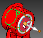 The Steering Wheel in Solid Edge with Synchronous Technology lets you move and rotate faces in a variety of ways. |
Once you switch a part over to ST, the plan is that there is no need to switch back to traditional history-based Solid Edge. If you open an ST part in traditional Solid Edge, all you get is a Parasolid body, the same as if it had been an imported part.
A Parametric B-Rep Model
Synchronous Technology works by manipulating the faces of the underlying B-rep (boundary representation) model in the same way that any other direct modeler works. This is why it treats any geometry, regardless of its origin, as native geometry.
With ST it is the software that lends intelligence to the data, so the data itself does not need to be intelligent. ST applies parametric relationships to the “dumb” faces of the model on the fly. As you make a change, you can either use or disable the parametric relations applied automatically between the faces.
This parametric scheme is accomplished through the Live Rules panel. It uses a type of geometry recognition to quickly find all the faces in the model that have one of a few relationships (such as tangent, coplanar, parallel, or perpendicular) and it allows you to maintain or disable those relationships as the model changes. Additionally, you can be more selective either through the Selection Manager or through the Advanced panel, where faces can be specifically disabled.
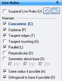 From the Live Rules dialog box, you tell Solid Edge with Synchronous Technology what operations you want to occur automatically when you select a face and work on it. |
You can also create persistent relations and driving dimensions such that some faces will always have a given relation. You can also apply dimensions that drive the model directly, without the intermediate use of sketches or features. Unlike dimensions in a typical sketch-based constraint system, you can choose which end of a given dimension to lock down and which end is free to move on the fly.
Why do you need sketches or features if you can apply relations and dimensions directly to the faces and edges of the solid model? You don’t.
“Best practice” rules are critical when working in history-based software, but they are completely eliminated by Synchronous Technology. One Siemens employee actually told me “we encourage hack and whack modeling.” In a history-based system it would be unthinkable to say that because how you get there is important. In ST it is not.
The Interface
One of the nicest things about Solid Edge with Synchronous Technology is that the interface is extremely limited. There are not a lot of tools for two reasons:
1) The main thing you do in ST is manipulate faces. During my visit, a Siemens employee said, “the fastest algorithm is one that does nothing.” Why invent complex ways of doing things? Simplicity of concept drives the development team.
2) Most of the interaction you have with the geometry is through a few very powerful tools: Steering Wheel, Live Rules, Quick Bar, Driving Dimensions, and the Selection Manager.
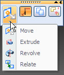 Quick Bar options that you see after you select a flat face. | 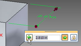 Using the Driving Dimensions dialog box, you size your model by applying the dimensions to the edges of a model directly. |
The Steering Wheel (see Figure 3) enables you to move and rotate faces. With a face or feature selected, you position the steering wheel so that the motion it makes (push-pull or rotation) moves the selection set in the desired way.
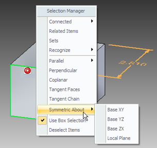 An example of using Selection Manager to select faces symmetric about reference geometry. |
Live Rules automatically selects other faces of the model based on the options in the dialog (see Figure 4). It highlights any conditions that are being used in the current selection. It might be more visually immediate if the other faces that are being selected were highlighted in some way on the screen. Any additional faces that are selected maintain their relationship to the original selected face when it is moved. Sometimes this selection set creates conflicts, and a little exclamation mark appears. This is the same sort of thing that happens in parametric sketches of history-based systems, except that ST never actually fails, it just shows the exclamation mark to tell you that you cannot move the selection set the way you are trying to move it. Live Rules can be disabled or you can manually remove faces from the automatically selected list.
The Quick Bar appears whenever you make a selection. It contains the options available for that selection (see Figure 5). Driving Dimensions are exactly what you hope they are: You simply apply dimensions directly to edges of the model. When you change the dimensions, the model updates (see Figure 6). The Selection Manager, shown in Figure 7, is a panel of options that enables you to use more sophisticated selection options when needed.
Matt Lombard is an engineering consultant specializing in plastic parts and complex shape modeling. Matt’s blog is dezignstuff.com/blog. Send comments about this article to [email protected].
Siemens PLM Systems
Plano, TX
Subscribe to our FREE magazine, FREE email newsletters or both!
Latest News
About the Author
DE’s editors contribute news and new product announcements to Digital Engineering.
Press releases may be sent to them via [email protected].


