Fast App: CAD Software Helps Formula One Team Run by the Numbers
Lotus F1 Team designers rely on Elysium CADdoctor for data transfer, software interoperability, reverse engineering and, of course, speed.


April 14, 2012
By DE Editors
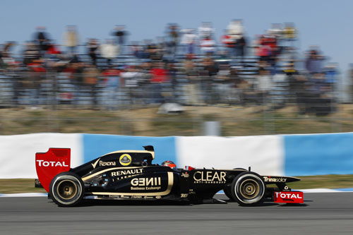
Did you know that Formula One (F1) racing can garner speeds of up to 220 miles an hour on the straightaway, and G forces can top five in the most extreme corners? It’s easy to see why this sport pushes both car and driver to the edge of what’s mechanically and humanly possible.
A cross between driving and flying, F1 “with its maze-like circuits “requires constant acceleration, braking and cornering that put tremendous stresses on the vehicle and demands on the car’s “pilot.” Drivers are literally form-fitted to their seats, wearing the car like a second skin. Reflexes need to be on instinct. Vehicles must be precision-tuned. Speed is king. As a result, there is no room for error with even the smallest detail.
At a minimum weight of 1,410 lbs. (less than one-third the average passenger car in the U.S.), today’s F1 racing machine “including nose, cockpit, wings and diffuser “embodies the almost-perfect aerodynamic balance of maximum down force (to keep the car in contact with the road) and minimum drag (to make sure it goes fast). In fact, design teams have become so effective at their aero analyses that the F ©d ©ration Internationale de l’Automobile, or FIA “the group that regulates the sport “is forced to pass new rules almost every year to keep the cars from going faster than is realistically safe.
To push the safe-speed envelope, Lotus employs more than 500 at its UK-based Enstone facility, northwest of London. Of that total, 60 to 70 designers work year-round on the design, testing and manufacture of the vehicle’s 20,000 “or so “interdependent parts.
“We’re a pretty sizeable facility for turning out just a couple of race cars,” admits Ian Goddard, senior engineer in charge of CAE.
For Goddard, the yearly design cycle involves balancing resources between tweaking the current model in the midst of the racing season, and major design revisions that will be part of the new car for the next season. His goal: to support the design team in maintaining on-track performance, while keeping more long-term developments also on track. This can be a difficult and stressful balancing act.
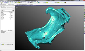 The F1’s seat in CADdoctor. | 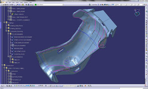 The F1’s seat in CATIA. |
“We condense the bulk of new design into the last quarter of the year, which, for the 2012 E20 model just launched in February, included more than 11,000 drawings,” says Goddard. “In the last week of build, we had parts turning up minute-by-minute, hour-by-hour, with day and night shifts fabricating the car and feeding all the technical information back to the design office.”
Given this condensed schedule “or “pressure environment,” as Goddard likes to call it “it’s obvious why speed and precision are important to more than just the car’s on-track performance during the 20-race season. Moving from concepts and models to carbon-fiber composite and alloy is time-critical, too. And the CAE team relies on a large set of engineering tools and processes for the fast, efficient and, above all, accurate flow of information through every stage of the development cycle.
It’s All about the Data
New car design for the Lotus F1 Team starts with a concept. During this initial stage, aerodynamic analysis, with traditional model building and wind-tunnel testing, works hand-in-hand with computational fluid dynamics (CFD) and its wind-tunnel algorithms that allow engineers to test design ideas on their desktops. Between the physical and virtual worlds, concepts are massaged as data is passed back and forth “from discipline to discipline and code to code. CAD models, capturing the car and component geometry, provide the interface for these data transactions.
Verification of the stresses and loads on structures, assemblies and components is then conducted via finite element analysis (FEA) software in another iterative looped process. As last steps, a final model that defines specifications and tolerances is sent out to a network of suppliers and manufacturers, and finished parts come back to be assembled into a race-ready car.
On the surface, it’s a seemingly simple straightaway of information flow: data in, data out, repeated a number of times. But according to Goddard, data transfer and translation is anything but simple when you dive into F1 details.
“With very advanced aerodynamic concepts, we might not get the perfect surfacing quality in the CAD models, so we need to clean them up,” he says. “Then, there are multiple CFD tools from both internal and external partners, and backward and forward handoffs from aero to CFD that we have to account for. There is also round-tripping between designers and FEA analysts, with the innate mismatches of spline-based CAD and mesh-based stress geometries. And at the end of the supply chain, manufacturers could be working on any of the many available CAD systems.”
Clearly, data is not standardized. Real-world F1 design involves digital inputs and outputs “at varying levels of complexity and cleanliness “that proceed in a circuitous path, mimicking the tracks that the actual cars navigate.
Steering the Data through Development
Back in the early days of CAD-based F1 design “the 1990s “engineers tried relying on their native CAD systems to do all the data translation work. But, according to Goddard, that came with a lot of uncertainty.
“There used to be endless discussions with suppliers about data quality, such as with untrimmed surfaces and rogue code, which you didn’t realize were in the model when you saved or exported it,” he recalls. “And you were never quite sure what the supplier was seeing. From a design viewpoint, that gray area was never reassuring.”
Realizing that software interoperability was critical in turning design data from gray to black-and-white, Lotus F1 Team’s first efforts at an upgrade involved CAD-conversion tools. But quality, reliability and efficiency improved considerably with the adoption of CADdoctor, a software suite from Japanese-founded Elysium, about a decade ago. The tool is designed to tie together data from all the various engineering software packages in a seamless, highly automated fashion. It does this by translating code into compatible formats, while ensuring that the data being transferred is error-free.
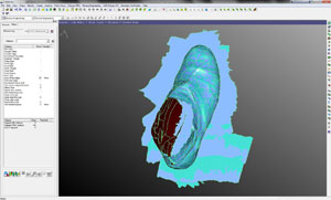 | 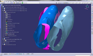 |
| Elysium’s CADdoctor was used in the reverse engineering of custom-fitted boot/pedal “packaging” in the Lotus. | |
The Lotus F1 Team now uses CADdoctor from one end of the design cycle to the other. At the aerodynamics concept stage, where CATIA V5 is the main design tool, the software is able to send data out to occasional external partners in common industry-standard codes, such as IGES, STEP or Parasolid.
“CADdoctor gives us an absolute guarantee of data quality,” says Goddard. “We use the software for visualization of complex geometries, and to refine or clean up the models.”
Once in the design environment, models move back and forth from CAD to FEA. Those handoffs can be complicated by the fact that Lotus F1 Team stress analysts, who have come from varied backgrounds, are allowed to work with their preferred tools, which can include Abaqus, Patran, Nastran, a range of Altair tools, and others.
“If we need linear, non-linear, composite, laminate, metallics, we’ve got a special application for each,” says Goddard. “At this stage, the data requirements can be a lot more diverse.”
CADdoctor also helps Lotus designers cross-convert between CAD versions, effectively downgrading models where things like filter radii or tangencies of surfaces might not translate properly. In addition, it’s used by stress engineers to do things such as simplifying parts to a basic, lower-level model so they can more easily load a complex assembly into FEA for meshing and analyses.
The software is most relied on, though, in supply chain data management. That’s where the team works with the best supplier for each job “whether they are a high-end CAD-based facility or a traditional hand-skilled operation. At every link in the chain, the tool has the ability to convert, clean and ship data to suppliers in a variety of standardized formats.
“That’s got two benefits for us,” says Goddard. “First, it’s a much more efficient way to liaise with suppliers. Second, it frees up expensive, high-end CAD licenses. It’s using the right tools for the right job.”
According to Goddard, the right job for CADdoctor includes a huge range of scenarios.
“A couple of weeks ago, we sent virtual cross-sections of the entire wind tunnel with all its hardware, instrumentation, and a full-car model for some outside consulting help,” he says. “When you’re dealing with data at that scale “if we didn’t use CADdoctor, our CAD system would quickly grind to a halt.”
The software is also extremely flexible. If the Lotus F1 Team needs to get complex data to a supplier immediately because they’re in deadline mode, the tool has a streamlined pushbutton approach. If the team needs to pay greater attention to geometric detail in the end-manufacturing process, they can use the software’s interactive and live walk-through features to visualize everything they’re processing and sending out.
“The Elysium suite’s range of tools and universal adaptability come in handy,” says Goddard. “We know CADdoctor can deal with anything we throw at it.”
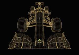 A wireframe of the 2012 Lotus Formula One E20. | 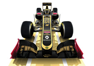 The 2012 Lotus Formula One E20 rendered. |
Data flow fuels F1 success
Let’s not forget for even a fraction of a second that speed matters in F1 racing. Out on the track, it’s easy to remember as the E20 launches from a standstill to 124 mph in just 4.9 seconds, with the engine cycling at 18,000 rpm. But on the drawing board, where designers must meticulously examine the car part-by-part, ply-by-ply, and data point-by-data point, it’s less obvious. So while it took 250,000 man-hours to design and build the 2012 vehicle, and there were about 20,000 design changes last year, the efficiency, accuracy “and yes, speed “of engineering data flow is critical, too. Without it, the Lotus F1 Team would have no chance in its pursuit of the World Championship, a title it won in 2005 and 2006.
“To compete, we need seamless, automated software interoperability “and tools like CADdoctor,” says Goddard. “So when we’re working in that pressure environment, we can just rely on the software to run in the background.”
Lotus F1 has partnered with Elysium since 2001, and is now in the process of renewing another multi-year agreement. At the same time, the two organizations are proactively looking at even more powerful ways to use the software for automation, supply chain logistics, and additional high-level reverse engineering. (See “Reverse Engineering the Lotus F1 Chassis.”)
“Partnering with Elysium brings us all sorts of benefits,” says Goddard. “We can call on their very best industry experts to help develop those processes, and push the limits of F1 performance even further.”
Reverse Engineering the Lotus F1 Chassis At 1,000 plies of molded carbon fiber and aluminum honeycomb, the chassis is the most complex composite laminate in the vehicle. It’s form-fitted to the driver, but still needs to accommodate an assortment of equipment “like steering and pedals, mechanical packaging, electrical components and a host of other items. With space and weight at a premium, detailed chassis structural specifications become vitally important. But certainty about those specifications is complicated by the fact that the composite structures in a F1 car (and in almost every other composite product) are basically handmade. When the team finishes assembling the jigsaw puzzle of carbon-fiber fabric and tape—even using sophisticated software and tools such as laser-ply positioning—they are left with variation in thickness and a lot of unknowns. To fully understand last year’s version to make improvements in next year’s design, Ian Goddard and his team reverse-engineer the chassis. The reverse engineering process starts with 3D hand scanning. This generates polygon-based point cloud data, with coarse shapes for the simpler areas and high-resolution polygons for the complex areas where various pieces of equipment need to get squeezed in. The scanned surfaces are then imported into CAD, where the resulting models can be “data heavy.” There might also be missing or overlapping areas, and even minute “holes” in the data because of things like reflections from the scanner. In other words, the models need a lot of cleanup. “Turning this heap of accurate, but virtually unusable, geometry into true engineering data is almost the Holy Grail of reverse engineering,” says Goddard. The alchemy of this data transformation rests on the suite of Elysium tools “and CAD support engineer Ashley Paxton from Processia Solutions, a Lotus F1 Team technical partner since 2001 specializing in software integration, customization, development and product lifecycle management (PLM). After the chassis is scanned, the data is aligned with the CAD model. But that process can be bumpy. “There can be various types of noise from things like dust, and numerous difference errors, such as sliver, short and long edges,” says Paxton. “CADdoctor fixes those things, and it can also find holes and mesh them automatically “papering over the cracks, so to speak “while keeping the same surface tolerance.” Designers used to split the model into smaller CAD chunks to clean things up. But it still took a long time to eliminate the errors. Now, using Elysium’s tools, Paxton can handle much larger quantities of scanned data more efficiently. “It’s far easier and quicker to run it through CADdoctor than trying to take care of it in CAD,” he says. Paxton also uses the same reverse engineering process, coupled with stress analysis, on parts manufactured quickly between races to ensure that the components are safe and ready for racing. |
Subscribe to our FREE magazine, FREE email newsletters or both!
About the Author
DE’s editors contribute news and new product announcements to Digital Engineering.
Press releases may be sent to them via [email protected].


