

July 13, 2012
By DE Editors
Fine, tiny detailing demanded by model railway enthusiasts requires mold-making tolerances in manufacturing scale models that are often tighter than those in the automotive industry.

PECO manufacturers the largest range of model railway track in the world, distributing to approximately 450 model shops across the United Kingdom, and exporting to more than 30 countries worldwide. New Products Development Manager Paul Hitchcock says PECO is renowned for quality and detail on its plastic injection-molded track and accessories.
When a model is scaled down, it becomes miniscule and can be extremely difficult to produce, but he says using Vero Software makes it easier to achieve. Working with a range of VISI modules not only provides greater accuracy, but also saves 30% of design time, while saving the toolroom computer numerically controlled (CNC) programmer even more time during the manufacturing process.
The materials used depends on what is being asked of the finished mold, and includes Uddeholm “Orvar Supreme” steel for the insert molded track tools, aluminum, Hasco 2311- 2312, and brass for interchangeable cavity inserts. The products are made from a range of polymers, including polythene for the track, acrylonitrile styrene acrylate (ASA), acetal, nylon and high-impact polystyrene (HIPS).
Tolerances for the track are extremely important, according to Engineering and Development Director Ben Arnold.
“We produce a lot of insert molded products with metal components that have their own tolerances,” he adds. “The tool has to sit very neatly and snugly around them to ensure there is no flash along the sides of the rails on the finished molded track product. In that respect, some of the tolerances for our tools are tighter than those I have worked with in the automotive industry.”
Hitchcock says the rail parts have to touch the tools precisely in the correct place to be right. “If they don’t touch, we’d get flash and that isn’t acceptable, so in reality we’re working to the nth degree” of precision, he says. While mold tools for most “lineside” products, such as station buildings and signals, are accurate to 10 to 20 microns, they generally use around 5 microns as a standard.
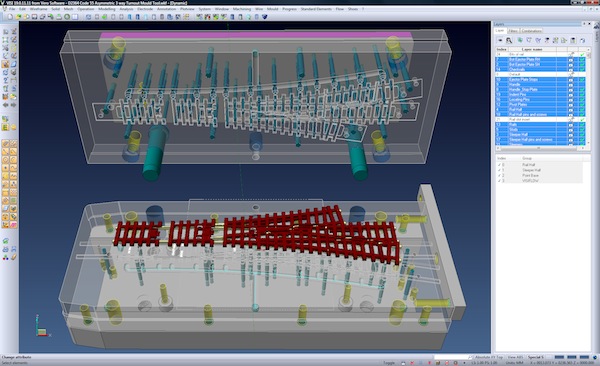
Hitchcock uses VISI Modeling, VISI Mold incorporating VISI Catalogues, and VISI Electrode to design the mold tools, having originally imported the product as SolidWorks data. The track needs a bespoke tool design, so he merges it with a blank tool template, creates the cavities, and adds ejector pins, guides and other standard components. For many other products, he uses VISI to design tools based on Hasco or Meusburger mold stacks.
He says creating the mold tool around the designed product takes approximately 30% less time than it did with the CAD/CAM system they used before switching to VISI in 2010.
“With the number of modifications and changes we go through during manufacture, the history tree of our previous system caused frequent problems,” he says. “But VISI provides concurrent design and manufacturing, meaning the design and toolpaths are easily modified.”
Features of VISI Modeling that stand out for Hitchcock include being able to import a model without affecting previous versions. “Also, it’s so simple to move a face, cut the body and create cavities.” He finds the layer structure to be particularly useful in migrating files to AutoSketch in DXF format.
VISI Mold’s ease of creating cavities and placing standard components, even into difficult shapes, gives Hitchcock confidence that the information he passes on to the toolroom is correct. Prior to using VISI, he says, he would sometimes feel that certain aspects of a mold design were not complete and may not work ““but now I know that if the mold is made to my design, it will work.”
Hitchcock says VISI provides another valuable facility: “If a cavity has been cut away without us noticing a face needed drafting, we can simply go back to the model of the mold tool and add draft to the appropriate face, knowing nothing else will be affected.”
When the mold design is complete, the process passes to the CNC programmer, who manufactures the electrodes using VISI Machining 2D and 3D.
“Some of our copper electrodes are so small, with such fine detail, that we have to separate sections out,” Hitchcock explains. “That used to cause a lot of trouble with our previous system, as we’d lose the detail by suppressing something that a number of other aspects are dependent on. But now we just extract what we want, without having to worry about everything else that’s generated the part.
“VISI has totally changed the way he works, in that he simply extracts the detail or faces using VISI Electrode,” he continues. “Previously, he would frequently have to make a 2D sketch from my 3D model, and use that to produce the electrodes.”
The machining part of the operation is made faster by the ability to have a number of instances open at any one time.
“We can set a calculation running, and then move on to another and another, with each toolpath calculating independently,” Hitchcock says. “With our previous software, we could only set one and have to wait “sometimes 30 minutes “for it to finish before we could move on. So we save a considerable amount of time on this part of the operation, too.”
Investment in machinery includes a Mikron high-speed machining center for making the electrodes, a Sodick CNC four-axis spark eroder with linear motors, and 11 injection-molding machines, mainly Engel and Arburg. They also have a laser ablation machine, which has been instrumental in producing molds for tiny N Scale lineside bikes. The mold was created in VISI, saved as an STL file, and imported directly into the laser machine for machining.
“VISI has made the manufacture of new mold tools much easier, and the whole process more efficient,” Hitchcock concludes.
More Info
Subscribe to our FREE magazine, FREE email newsletters or both!
About the Author
DE’s editors contribute news and new product announcements to Digital Engineering.
Press releases may be sent to them via [email protected].


