

Latest News
April 14, 2012
By By Guus Bertels
 Extracting energy—either petroleum or natural gas—is a complex process that itself consumes voluminous amounts of energy. Much of this goes toward fuelling on-site generators that power the cooling systems needed to chill the gas or oil as it emerges from the well heads.
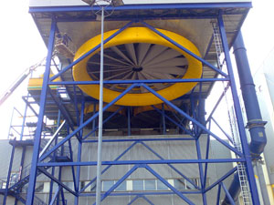
Inside a gas- or oil-field cooling system, fans up to 33 ft. in diameter move air across cooling coils (“bundles”) that carry the product. Dozens, or even hundreds of fan systems may be required, along with megawatts of electrical power to run them. Often, noise issues are as important as cost challenges. These large industrial plants are subject to stringent noise regulations.
The fans used in such applications historically have delivered a maximum efficiency of about 50%. What would happen if that efficiency could be increased to 80% or more? What would be the effect on noise output if the fans could run at a lower rpm, and still do the job? Fewer fans could do the same work with less energy, less noise and lower operational costs.
The design engineering team at Bronswerk Heat Transfer BV (Nijkerk, The Netherlands) set out to create a new generation of air-cooled cooling systems that would solve the age-old problems. The company is renowned for its high-capacity air-cooled coolers that are widely used in the energy industry. We chose a proven concurrent computational fluid dynamics (CFD) toolset for analysis and validation.
Over the past few years, we have used both CFD tools and physical measurements to characterize the behavior—particularly the aerodynamics—of large air-cooled cooling systems. We have learned that concurrent CFD often can produce data that would be impossible to acquire with measurements because of physical constraints, the Heisenberg principle and other factors.
The new Bronswerk cooling solution includes fans and housings that take their technology cues from gas turbines, aircraft wings, and a generous helping of homegrown creativity. The practicality of these creative touches was validated quickly and accurately with CFD. In addition to their purely quantitative output, the CFD simulations enabled us to explore bold ideas—without risking project budgets and schedules.
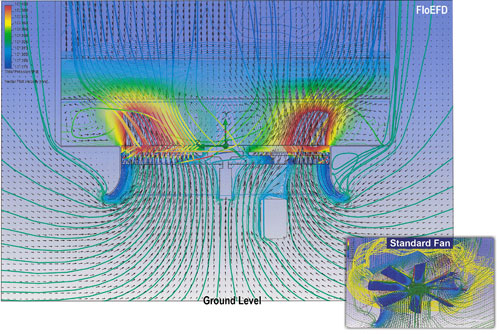
Figure 1: These FloEFD images clearly reveal perturbations in the air flow
through a high-performance, eight-bladed air-cooled cooling assembly.
Air Flow, Before and After
Figure 1 is a CFD plot depicting the air flow behavior of a ground-facing fan used as our reference. The vector arrows in the large image represent the direction of the air flow, while the color scale reads pressure. The colored lines highlight localized pressure trends including “eddies” and backflows. The eight-bladed fan is among the best in its class, but perturbations like these detract from the desired output flow and are a source of noise as well.
Figure 1 is a simulation view produced by Mentor Graphics FloEFD Pro, a concurrent CFD application. Because concurrent CFD tools embed in a host MCAD environment (in this case Pro/ENGINEER, now Creo Elements/Pro) and work directly with the MCAD geometries, users can run, modify and re-run simulations in quick succession. Moreover, a full-featured concurrent CFD package automates crucial (and esoteric) steps such as mesh design and cavity modeling, enabling staff designers to perform advanced analyses.
Figure 1 reveals an eddy just above the drive motor, matched by an equivalent “shadow” on the outlet side. Small, but high-intensity eddies appear to be forming at the edges of the inlet funnel. In the inset photo, the fan is producing a maelstrom of eddy currents due to vortices at the tips of its blades. Conventional fans can dissipate up to 50% of their energy at the blade tips alone. The reference fan does better than this, but its CFD plots, which were consistent with the best available field measurement data, prove that there is still room for improvement.
Redefining Fan Blade Design
Improving this performance was a system-level effort that involved redesigning the fan blade configuration, the inlet/outlet architecture, and more.
A departure from ordinary fan design and its reliance on straight blades was needed. From our experience and study of fan design theory, we knew that the blades should be tuned to the actual local directional flow and the magnitude thereof. After considerable research and repeated simulation, the team moved to a three-dimensional blade profile with a substantial—about 50 °—curvature between the hub and the tip. The twist was developed with the help of an in-house analysis application, and its performance validated with concurrent CFD plots.
The CFD process helped us optimize the blades’ aerodynamics (thrust/drag ratios) across their entire span as well. And the number of blades was doubled to 16, reducing vibration and noise.
The curved, tapered blades were a great stride, but the optimization didn’t end there. Our design team experimented with the up-swept “winglet” concepts used on jet airliners to minimize vortices on the wing tips. The resolution and accuracy of the concurrent CFD toolset were crucial here, since the boundary layer at the blade tips was on the order of millimeters thick within an overall scale four orders of magnitude larger. The fan’s mechanical situation is unique because, in contrast to the two opposing points of an airplane’s wings, the 16 fan blade tips form a circle. This lends itself to joining all the tips into one solid ring on the circumference.
Figure 2 depicts the results of the design team’s work, now known as the Whizz-Wheel. This novel device is lighter than existing designs and actually moves more air while spinning at a lower rpm.
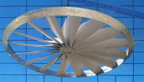
Figure 2: The Bronswerk Whizz-Wheel (seen here suspended from a crane)
uses a continuous “winglet” structure on the blade tips to reduce air friction,
energy loss and noise.
Smoothing the Air Flow Path
The Whizz-Wheel fan is a striking innovation, but the whole cooling system’s elements interact with each other and with ground effects as well. One particular challenge was the transition between the incoming air flow and the rotating fan. In the field, the fans and cooling bundles are mounted several yards above the ground on steel frames. Even with a gap of this size, ground effects must be considered. The fans are downward-facing and the air is drawn upward. Our design team literally had to “think outside the box” to redesign the inlet and smooth the air flow path toward the spinning blades. The standard fan’s enclosure and bell-shaped inlet were bending the flow, causing efficiency losses, high turbulence, and noise (see Figure 1).
Based on prior experience in aircraft design, we realized that getting the air flow to work at the blades was a matter of controlling the boundary layer behavior at the mouth of the intake. This lesson, drawn from jet turbine engine architecture, is not surprising considering the fan’s unmistakable resemblance to a turbine engine’s intake fan.
Performing CFD analysis directly on the MCAD models of their proposals, the engineers were able to smooth the inlet ring geometry into a “donut” profile that rounded out the abrupt transitions of the bell-shaped inlet. The CFD plots in Figure 3 confirm that the new inlet configuration is far less disruptive to the incoming air flow, even when ground effects are present.
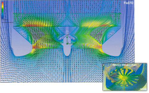
Figure 3: The Whizz-Wheel air flow conforms closely to the new inlet profile
and blade structures, reducing noise.
As the vector arrows and flow lines indicate, the air flow entering the system follows the rounded inlet almost ideally, while the exiting flow is far more uniform and symmetrical than in the standard fan. The new geometry keeps the incoming flow intact toward the blade tips, where the blade velocity is the highest. The inset image underscores the flow uniformity, and also speaks of dramatically reduced vorticity and turbulence at the blade tips. The completed design reduces noise by fully 50%. Moreover, the new inlet is more compact in height than its predecessors.
Physical vs. Virtual
Physical measurements were essential to the project’s success, but couldn’t produce the needed data in every case. With simulation, we were able to look at static pressure distributions through a flow field and get information on the total pressure, which is a direct measure of the entropy in the system. A loss in total pressure is energy loss, and CFD delivers a color picture of where the losses are. We could never have hoped to measure that with physical measurements alone.
Other cooling system elements, such as the bundles and the settling chamber, are beyond the scope of this brief introductory article. But they were similarly analyzed and engineered with the help of CFD simulations. Whizz-Wheel-based cooling systems are now breaking all industry records for energy efficiency, noise reduction and weight savings.
Guus Bertels’ experience in the engineering field began in 1963, and by 1970 he had earned bachelor’s and master’s of science degrees in mechanical engineering, plus a professional engineer credential in Canada. After several years of laboratory work in aeronautics, Bertels founded a technical and scientific analysis firm that consulted in the development of more than 50 patents. He has also worked in the academic field as a professor of research in thermo-mechanics and control theory. Since 2005, Bertels has been the associate director of advanced design and analysis at Bronswerk Heat Transfer BV.
MORE INFO
Bronswerk Heat Transfer BV
Creo Elements/Pro
Mentor Graphics
Subscribe to our FREE magazine, FREE email newsletters or both!
Latest News
About the Author
DE’s editors contribute news and new product announcements to Digital Engineering.
Press releases may be sent to them via [email protected].


