FEA: Behind the Scenes of Machines
Multi-disciplinary analysis with Abaqus, ANSYS, Algor, NEi Nastran, NX, and SimXpert FEA smoothes design of manufacturing machinery.


Latest News
June 1, 2010
By Pamela J. Waterman
The next time you handle a piece of paper, pick up a soda can, or turn on a lamp (meaning probably sometime in the next five minutes), think about the equipment that made that sheet, container, or fixture. Then think again about optimizing that machinery in terms of component strength, contact forces, part clearance, thermal expansion, and long-term durability. This is the world of manufacturing design for machinery.
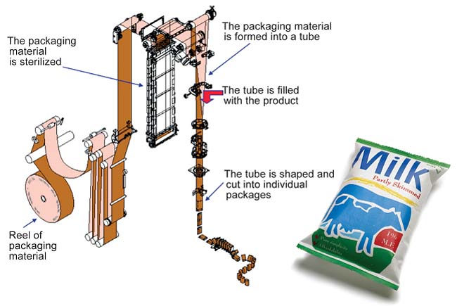 A system performance schematic (left) of a filling and packaging system for an aseptic liquid container, was simulated with Simulia Abaqus FEA software. The simulated consumer packaging for milk, formed from flat stock, filled and sealed with the automated system (right). Image courtesy TetraPak |
Finite element analysis (FEA) software plays a key role in understanding the operation of machinery that contains hundreds to thousands of parts, many of them in constant motion. DE examines how several analysis packages accomplish this impressive task.
Top Requirement: Accurate Handling of Critical Details
What do manufacturing users most often require in designing their complex equipment? Developers of NEi Nastran will tell you it’s the capability to handle advanced surface contact, fatigue issues, and composite materials. Allan Hsu, an NEi Software application engineer, says that accurately modeling contact conditions is critical in evaluating the structural integrity of equipment ranging from scissor lifts to conveyor belts.
Hsu explains, “Assuming that parts are ‘glued’ at joints or that sliding is minimal between certain parts will tend to affect the load path of the structure, resulting in less accuracy of the FE analysis. Defining true surface contact, where parts can bear up against each other, separate, or slide against each other is the most accurate choice. A prospect in this industry looking for an FEA package should make sure they will have true surface-contact capability, not outdated contact approximations that define the stiffness between nodes.”
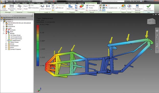 Autodesk Inventor Professional software was used to perform structural simulation on a Techman-Head engine stand, used to support the engine of an aircraft during servicing. The simulation results helped to validate the predicted deformation of the stand under load. Image courtesy of Techman-Head Group |
Equipment manufacturers also need to know whether a certain design will meet desired service life expectations. With the NEi Nastran interface, users can take a structural analysis (for example, a linear static analysis) and, just by adding material fatigue properties and loading cycles, automatically evaluate fatigue damage and fatigue life (both high and low cycle).
A third aspect important to designers needing strong yet lightweight structures is that of analyzing composite material behavior. New FEA users should check to see if the software can perform such functions as predicting layer de-bonding and fiber failures.
Check out NEi Software’s homepage to read useful discussions categorized for designers who are new to FEA, experienced with general FEA or accustomed to a different flavor of Nastran. The company’s personalized customer service also gets high marks from users.
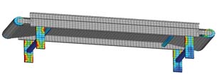 This is a simulation of general stress on parts during typical operational loading of a conveyor belt (125 lb object). Image courtesy NEi Software |
Nonlinear behavior is common in the materials processed by complex manufacturing equipment. SIMULIA’s Abaqus FEA software takes direct aim at understanding and predicting all possible interactions; consequently, the machinery itself must be designed with this in mind. A common example involves the roll-fed paper or plastic used in equipment that simultaneously creates and fills an orange-juice carton.
David Cadge, of SIMULIA’s electronics and consumer products division, points out that when working with bottle- or container-handling machinery, simulations can quickly become complex. The analysis of how the packaging material moves through the system must incorporate not only the behavior the fluid involved, but also the changing fluid-structural interactions over time. Thus, every component of the machinery, whether metal or plastic, must be evaluated as to how it responds to those conditions: how much tension should you put on the material as it is folded, shaped, sealed, and cut? How quickly can you run the machine to do so? What are the thermal and mechanical limitations?
Users need robust, accurate, reliable solutions says Cadge. Abaqus offers this as well as direct geometry import and simple assembly setup. He adds, “This makes it easy to add parts or copies of parts into the model, for example when multiple, identical bottles are traveling along a conveyor belt. We also have fast, compatible solvers needed for the diverse simulation applications of this industry, some suited to implicit solutions, some explicit, and others requiring both for efficiency.”
Integrated Analysis in the Big Picture
According to Richard Bush, marketing director for Siemens PLM Software Digital Lifecycle Simulation group, when looking at the manufacturing process from a higher level, speed ultimately drives every decision. Design engineers will tell you there are a huge number of changes made late in product design, which translate into last-minute changes to manufacturing machinery—and those changes must be precise. CAE software must therefore be integrated in the full process to be reliable and respond quickly. “Wait time is death time,” observes Bush.
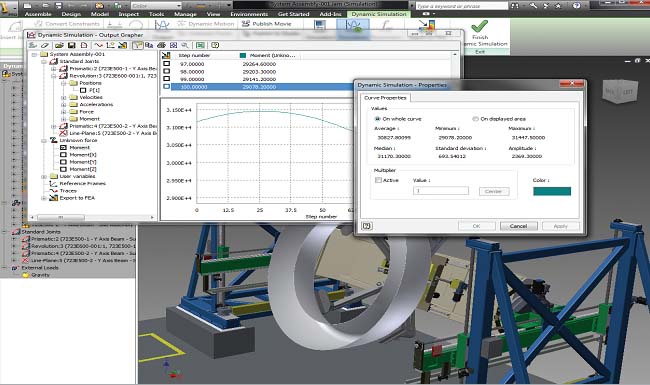 The Dynamic Simulation tools included in Autodesk Inventor Professional software were used to study a GEMCOR nacelle system, a fastening system designed for the production of engine nacelle assemblies used in the aerospace industry. In addition to simulating the motion of the fan cowl during manufacturing, the “Unknown Force” functionality was used to determine specifications for the optimal motor size required to operate the system efficiently. Model courtesy of GEMCOR. |
Many machine builders start by combining standard modules and making changes to suit the requirements for manufacturing a specific product. Siemen’s Synchronous Technology supports this task across all stages, first offering feature-recognition, accelerating edits to 3D part files (some of them “dumb”) created on different CAD platforms. Siemens PLM Software NX analysis software then gives mechanical designers access to advanced analysis tools by combining controls and motion behavior with FEA results.
Speed of actual operation is also critical. “A lot of companies are being challenged to make machines go faster,” says Bush, “yet the materials they handle may not be simple, and the analyses must cover ]the effects of] many different disciplines.” He explains that to analyze moving parts FEA software may need to incorporate multi-body dynamics that go beyond simple rigid kinematics and clearance-checking, accounting for machinery parts flexing during use, thermal effects as moving parts heat up and expand, response of control electronics to heat, and even the behavior of the part or parts being manufactured. For example, analysis of a roll of paper moving at high speed through a printing press may actually need to include fluid effects.
Siemens PLM Software realizes that a customer may have one analyst per 50 designers, so the vision is to make complex simulation a part of the process at a level designers can use. It must capture and reuse existing designs, work with analysis codes from other vendors, be scalable to manage assemblies of thousands of parts, and ultimately be reliable.
FEA capabilities deeply embedded in a CAD environment are a key to success at Autodesk, too. The company’s acquisition of Algor Simulation software expanded the possibilities for analysis across a spectrum of products and therefore users, including the upfront designers. Autodesk’s Bob Williams, the company’s Algor product manager, says that industrial machinery is the bread and butter of simulation, so it was important to offer solutions to fit all needs.
Autodesk’s simulation technology is introduced in Inventor, where designers can investigate structural responses, kinematic behavior and basic vibration responses. From there, as needed, users can move up either to Algor CFD for fluid analysis or Algor Mechanical Event Simulation (MES), which includes flexible multi-body analysis and can analyze such details as rubber-gasket functions or long-term fatigue.
Williams sees more non-experts and non-dedicated users involved in simulations, so a number of issues are critical for their success. To handle geometry coming in from different CAD packages, Inventor includes many translators while Algor MES works directly with multiple CAD formats.
Scalability is also important. Williams explains that with some packages, “Jumping from linear static stress and linear vibrations to full-blown motions may only be available through a different interface or workflow. Knowing that you can expand as your needs expand without having to learn a new workflow (or hire new people) —that’s what supervisors want to hear to minimize costs.”
Lastly, he says, prospective customers should consider ease of use—not just button clicks, but what other resources are available to help you get up and running and be productive. Since the actual simulation technology (i.e., linear static stress) itself is fairly similar between a lot of different tools, these factors become the important differentiators. Autodesk offers its Users Guide, tutorials, and white papers online with no user registration necessary.
Software developers at ANSYS draw on their decades of experience to understand what users need today and will want tomorrow. Thierry Marchal, ANSYS’ industry lead, says that designers want to move in the direction of simulating assemblies with thousands of parts but to model each part and its interaction with the environment is a complex, long-term project. What is generally done today is to model just the parts that would create bottlenecks in machinery operation, then add more parts as possible.
Beyond simplifying the complexities of the assembly, says Marchal, performing an accurate simulation depends first on making sure there is a good software environment for importing the CAD geometry plus a relatively automatic way to generate a quality mesh for each part. “Make sure that the interaction between the parts (such as) friction and sliding is in the model, then start with a relatively simple model and a simple load, rather than a complex non-linear material or load.” He adds that the system and the path of motion are the most important considerations.
Given these starting points, Marchal says users should make sure the software in question can handle any necessary physics (such as the behavior of lubricating oil) as well as assemblies with a great many parts. With recent advances in computing power from such techniques as cloud computing, it would be a shame not to have software that can take advantage of this, both technically and in terms of licensing. Lastly, the package should include data management capabilities that let users get new results from making minor geometric changes without having to rerun a full simulation.
A Classic in the Field
Several years ago, Nastran FEA software from MSC.Software became part of the company’s SimXpert integrated simulation environment, handling both multi-body designs and multi-discipline physics for linear and non-linear conditions. SimXpert capabilities that may be relevant to machinery designs include modeling and analysis of gears, bearings, pumps, seals, pneumatics, hydraulics, rotating machinery, and control systems.
A SimXpert analysis can incorporate flexible body representation, contact modeling and vibration and durability studies. Its Workspace structure lets users in different disciplines model and analyze just those parts that are relevant to their problems, and only brings up menus for the chosen task or tasks. For example, the Motion Workspace lets users define the allowable degrees of freedom between moving parts, the contacts between parts, and any forces applied to or between parts. Results are viewable in both chart and animation formats.
The Human Factor
The more flexible the FEA package, the greater the chance that users will have questions regarding specific applications. A fundamental requirement for efficient usage is therefore a fast, friendly, capable customer-support program. Sliding contacts and non-linear materials aside, the real deal-maker may just be the level of personal guidance you can expect from the FEA vendor. Quiz the current customers. Idle machinery loses money, so great support can be the deal maker.
More Info:
ANSYS
Contributing Editor Pamela J. Waterman, DE’s simulation expert, is an electrical engineer and free-lance technical writer based in Arizona. You can send her e-mail to [email protected].
Subscribe to our FREE magazine, FREE email newsletters or both!
Latest News
About the Author
Pamela Waterman worked as Digital Engineering’s contributing editor for two decades. Contact her via .(JavaScript must be enabled to view this email address).
Follow DE

