

January 1, 2009
By Jerry Fireman
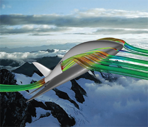 FieldView enabled designers to see airflow structures like vortex cores and turbulence to quicklyimprove the performance of their concept airframe. Image courtesy of Intelligent Light |
Not much has changed in the design of airframes over the last 50 years. After all, manufacturers have gained a tremendous amount of engineering and manufacturing experience based on designs that have proven themselves over that time period. Certainly, the systems engineering developed and applied throughout the aviation industry has increased both safety and reliability over these five decades.
But a small team of engineers decided to start with a blank slate and use the latest computer-aided engineering tools to optimize aircraft geometry from a purely aerodynamic point of view. Enter Koni Schafroth and Team SmartFish.
With the goal to significantly reduce drag, Schafroth decided to eliminate the aerodynamic interference where wings meet the fuselage. He developed a 3D shape that incorporates wings and fuselage in a smoothly flowing form that, to his surprise, resembled a fish. Fishes’ fins are attached on their trunk at a position just forward of the maximum thickness of their body, the point where pressure equilibration occurs. The resulting increase in the aspect ratio reduces the induced drag coefficient.
Schafroth spent months researching fish in books, at aquariums, and even went snorkeling to study how fish move through the water. While he found the vast natural variety of fish fascinating, it was one of the world’s fastest fish, the tuna, that provided the final inspiration for his design.
Creating a Unique Design
As Schafroth puts it, two technological developments enabled his team to develop a more efficient and safer craft than conventional airplanes. “The first and most important,” he says, “are simulation tools that allow us to evaluate the performance of conceptual airframe geometry and visualize the airflow around the plane in a way that helps us understand its performance to a higher level than was possible in the past. We can also view the performance of one shape overlaid on another to identify tiny differences that will help us quickly compare two design alternatives. The second is the advances in computerized numerical control milling that allow us to easily produce any shape we can conceive.”
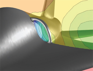 Inlet placement and design is critical to the efficiency of SmartFish. Using FieldView and its unique Partial Integration feature, mass flow rate through the inlet can be computed accurately.Image courtesy of Intelligent Light |
While acknowledging that airframe manufacturers have been using simulation tools over the past three decades, Schafroth notes that simulations that previously ran for hours on supercomputers and required teams of highly trained specialists can now run on modern PCs in a few seconds.
“Aerospace engineers with a background in fluid dynamics can solve relatively fine meshes and complex geometries using modern workstations or laptops in just hours of processing time,” he says. “We use the CFD++ solver ]Metacomp Technologies] because of its ability to converge quickly and provide highly accurate results using a coarse mesh that is ideal for use in the conceptual stages of design. We use FieldView ]Intelligent Light] for postprocessing these results. By coupling the CFD codes with an optimizer software like modeFrontier ]Esteco] and a mesh deformation software like Sculptor ]Optimal Solutions], an automated process can produce simulations and results of more than 100 different design variations overnight.” That’s a nice result when you are creating unstructured tetrahedral meshes ranging from 300,000 to 2 million cells.
Schafroth credits FieldView’s ease of use and visualization capabilities with providing the team an advantage in getting more information in less time. “In addition,” he says, “FieldView’s user interface is intuitive enough that I can go without using the tool for several weeks and then come back and pick up right where I left off using restart files with new or existing data.”
When Schafroth first applied this simulation capability, one of the first tasks was to determine how closely it reflected physical reality. The team compared wind tunnel tests using surface oil flow techniques on a model milled using Mastercam from an NX model (Siemens PLM Software) to simulations using CFD++ and FieldView and discovered that the simulation very closely matched the physical testing results.
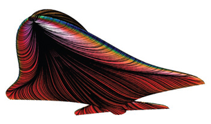 This visualization illustrates the SmartFish’s surface pressure distribution with overlaid surfacerestricted streamlines on its lower surface. Image courtesy of Intelligent Light |
Increasing Efficiency
The SmartFish is optimized for transonic speeds, meaning it flies at subsonic speeds but flow over the wing is partly supersonic. Working in FieldView, Schafroth quickly evolved the design based on his original concept of a 3D design with a low aspect ratio. FieldView goes beyond conventional postprocessors by identifying flow structures such as vortex cores in the CFD results and generating streamlines that make it easy to visualize the airflow over the surface. These streamlines, in most cases, provide the ability to quickly understand why a design is performing the way it is so engineers can immediately improve it.
Another unique feature of FieldView is the ease of comparing alternative designs. “We can make designs transparent and superimpose them on top of each other in order to quickly highlight differences in flow and pressure and determine if our latest design iteration is better or worse than the last one,” Schafroth said.
Based on the team’s simulations, Schafroth developed the external contours of the plane to provide smooth flow around the entire aircraft without flow separation to minimize drag. The shear layer that develops from the leading edge at high angles of attack (AOA) tends to wrap into a tightly bound vortex that has a high local velocity and low pressure. This so-called vortex lift makes a very significant contribution to the total lift. At some downstream position, which is dependent on the angle of attack and past motion, the vortex suffers from a rapid deceleration and expansion of the vortex core known as vortex breakdown.
Vortex breakdown is very often asymmetric, causing a loss of lift in just one wing. Schafroth designed the leading edge of the SmartFish wing to delay vortex lift to higher angles of attack. A secondary effect is that vortex breakdown at higher angles is now always symmetric.
SmartFish has an astonishingly high lift-to-drag (L/D) ratio compared to conventional aircraft designs, but is able to carry greater loads because of its lighter weight. “This aircraft looks like a Porsche, but it has the utility of a VW bus,” Schafroth said.
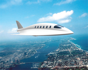 SmartFish corporate jet concept design. Image courtesy of Intelligent Light. |
Improved Safety & Lower Costs
SmartFish’s unique aerodynamics make the aircraft safer. Unlike conventional aircraft, there is no stall when ice forms on the surfaces because vortex lift is created at lower AOA when ice is present. SmartFish also does not require complex lift systems like flaps and it has greater margin between stall and buffeting than conventional aircraft. It also has a high critical Mach number, placing the point at which it might lose lift at a higher altitude and greater speed than conventional designs.
SmartFish will be less expensive to build and maintain than conventional aircraft for several reasons: There are no complex wing-fuselage joints — highly loaded structures — at 90 degrees to one another, no intersections with fillets, and trailing edge control surfaces on the elevator have simple hinges rather than spoilers, flaps, or slats.
Last spring, the SmartFish team, together with the German Aerospace Research Centre, built HyFish, a small unmanned plane based on the SmartFish design powered by a fuel cell. HyFish has a wingspan of 1m, a total length of 1.3m, and a weight of 6.1kg. The fuel cell system weighs 3kg and has an electrical output of 1kW. The plane was flown at speeds close to 200 kph and demonstrated excellent handling and aerobatic stunts without losing control.
Schafroth’s next challenge is to secure funding to design, build, and test a full-sized manned version. He hopes the combination of investment, creativity, engineering skills, and capable and accessible simulation tools will bring SmartFish to reality.
More Info:
CNC Software, Inc.
Tolland, CT
Esteco
Trieste, Italy
Intelligent Light
Rutherford, NJ
Metacomp Technologies
Agoura Hills, CA
Optimal Solutions Software
Idaho Falls, ID
Siemens PLM Software
Plano, TX
Team SmartFish
Bern, Switzerland
Jerry Fireman is the founder of Structured Information. He has written about all aspects of the CAE industry for more than 20 years. You can send comments via e-mail to [email protected].
Subscribe to our FREE magazine, FREE email newsletters or both!
About the Author
DE’s editors contribute news and new product announcements to Digital Engineering.
Press releases may be sent to them via [email protected].


