Geometric DFMPro
Design for manufacturability formalizes rules for designs so that, in theory at least, engineers will design parts that manufacturers can easily make.


Latest News
July 2, 2012
By Mark Clarkson
Design for manufacturability (DFM), sometimes also known as design for manufacture, is a perfectly straightforward idea: Products should be designed so that they can be manufactured. Moreover, they should be designed so that they are as easy and inexpensive to manufacture as possible. For machined parts, for example, you need to be concerned with the material, with tool accessibility, and with the depth and shape of cavities and holes. Injection-molded parts need to slip easily out of their molds.
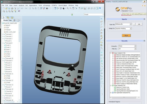 |
| DFMPro’s Injection Molding module allows users to validate designs against standard direct-for-manufacturing practices. |
For anything other than the simplest parts and products, DFM can involve volumes of rules that can be hard to remember and time-consuming to check. Design reviews consume the time of experts. If a part fails design review, it heads back to the designer to be redesigned. This rework is expensive in terms of both time and money.
Enter DFM software such as DFMPro from Geometric Global. DFMPro is a DFM tool that runs within your CAD software: Creo Parametric (formerly Pro/ENGINEER), Dassault Systemes SolidWorks and Siemens NX.
A Rules Referee
DFMPro acts something like a spell checker for your CAD designs, providing quick checking of copious design rules to improve the manufacturability of parts and assemblies, and to reduce their manufacturing cost. It comes out of the box with more than 100 configurable rules—pulled from various handbooks, guidelines and DFM experts. You can customize the application to add more.
DFMPro automatically recognizes key features from your CAD designs. You don’t have to tell it where the ribs and bosses are; it will locate them on its own.
Run DFMPro and, after a few seconds or minutes, it returns a hierarchical, interactive list of your problem areas. You can see at a glance how many rules your design breaks, what those rules are, and where each instance of the problem is. You’ll also get a list of all the rules your design passed, as well as those rules that don’t apply to this design.
Click on a broken rule, and all instances of the problem are highlighted on your CAD model. Click on a problem, and you’ll zoom in on that feature and receive a description of the issue.
The descriptions go way beyond “FAILURE: RULE 27.” They give the design engineer actual useful information such as, “There is no fillet at the base of the boss, whereas it is recommended to have a fillet 0.25 times the nominal wall thickness of the part.”
DFMPro will even explain the rules. It will tell you, for example, not just that your cavity doesn’t have the minimum draft angle, but what draft angles are and why they are important, complete with illustrated examples and recommendations. This should actually help new design engineers to understand and implement proper design practices.
The Ability to Customize
The rules can be tweaked within the application’s rule manager interface. Simply click a check box to enable or disable the checking of individual rules (deep holes, hole alignment, uniform wall thickness, etc.). You can also change the parameters for the rules, varying the minimum draft angle, or the preferred ratio of rib width to wall thickness. You can prioritize the rules by their “criticality,” which runs from Insignificant to Critical. There’s no scripting involved; everything happens in straightforward dialog boxes.
Not all rules will apply to every design, so sets of rules can be saved under unique file names. You can choose which ones to use at run time.
Four Modules
DFMPro’s design checking comes in four distinct modules. When you run DFMPro, you select the module from a drop-down list:
The Injection Molding modulechecks include minimum draft angle, minimum radius at the base andtip of bosses, wall thickness, maximum cutout area and undercuts.
The Sheet Metal modulechecks for problems with distances between holes, bend and hemradii, slot and hole size, etc.
The Machining modulehandles drilling, prismatic milling, and turning. It checks forproblems such as deep holes, narrow slots, pockets with bottomchamfers and flat-bottomed holes.
The Assembly module checksminimum clearances, both globally and between specific components,as well as issues such as alignment between holes and fastenerprojection.
The results of DFMPro’s analysis can be exported and shared with others as eDrawings, XML documents or Microsoft Excel spreadsheets.
Parting Thoughts
DFMPro follows the trend of pushing more analytical technology—finite element analysis (FEA), for example—downstream to the design engineers, allowing them to check their work more thoroughly before passing it on down the pipeline. DFMPro allows design engineers to identify manufacturing problems early in the design and manufacturing process. The program is easy to learn and to use, and quickly provides interactive, easy-to-navigate feedback to the design engineer, spotlighting areas and features that are potentially difficult, expensive and impossible to manufacture.
DFMPro doesn’t solve your design problems; it just highlights them. Still, it should significantly cut down your product design/redesign iterations and the amount of expert time you need to apply to design reviews. It’s definitely worth a look.
Contributing Editor Mark Clarkson is DE’s expert in visualization, computer animation, and graphics. His newest book is Photoshop Elements by Example. Visit him on the web at MarkClarkson.com or send e-mail about this article to [email protected].
More Info
Subscribe to our FREE magazine, FREE email newsletters or both!
Latest News
About the Author
Mark ClarksonContributing Editor Mark Clarkson is Digital Engineering’s expert in visualization, computer animation, and graphics. His newest book is Photoshop Elements by Example. Visit him on the web at MarkClarkson.com or send e-mail about this article to [email protected].
Follow DE

