Get a GRIP on EMI
Electromagnetic interference is highly problematic for designers of all types of products and systems--and it's growing, thanks to the proliferation of electronic components.
Latest News
October 1, 2011
By Barbara G. Goode
“Everybody has to pass. And everybody has trouble,” says Steve Newson of Newson Consulting Inc., a specialist in the field of electromagnetic interference (EMI; also called radio frequency interference, or RFI) with clients in almost every industry. Newson is referring to the fact that all products need to meet standards for electromagnetic emissions—and that EMI can be a significant problem for systems designers.
An Increasing Problem
Any object that carries rapidly changing electrical currents or voltages can generate EMI, which has the potential to degrade the performance of another electrical device.
Dr. Bruce Archambeault, an IBM Distinguished Engineer, lead author of the EMI/EMC Computational Modeling Handbook and author of the book PCB Design for Real-World EMI Control, notes that EMI is a subset of electromagnetic compatibility (EMC), a field that studies how devices and systems can perform without generating unacceptable EMI levels. Of course, any work with printed circuit boards (PCBs) requires the generation of signals, and Archambeault says it is best to reduce EMI at its source.
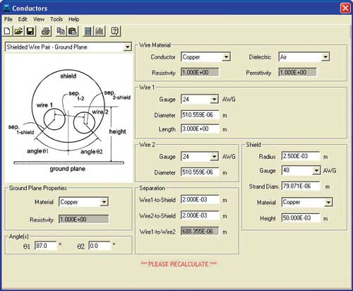
The Conductor Form is an input screen used to define the dimensions of the cable for the system being analyzed. It is typical of many of the EMI Analyst input screens. Image courtesy EMI Software LLC.
“Emissions start on circuits and leak out through seams and cables, which radiate them,” he explains, saying that faster rise time leads to higher frequency of emissions. As frequency increases, slots and seams become more effective leakage points.
“At 10 MHz, you might not see much effect, but at higher frequencies—especially in the gigahertz (GHz) range—it is a different story,” he says.
If the product you are designing is a small pager or similar device running at a relatively low frequency (say, below 10 to 50 MHz) with no wires attached, it is pretty safe as far as emissions go, says Archambeault. But radios and telephones are extremely sensitive. In general, the larger the device or system, the more wires and cables are involved—and the higher the frequency range, the more potential for EMI trouble. A product operating in the GHz range becomes almost impossible to shield, explains Archambeault, adding, “High-speed digital electronics can radiate enough emissions to be received by their own internal antennae.”
In addition, Archambeault says, a cable can become the most important part of an antenna. Newson agrees: “A lot of people think that the most difficult EMI problems are related to PCBs and box shielding, but the biggest problem is cables,” he says. “Cables act as antennae.”
As Newson explains, the potential for trouble is increasing. “In the past 20 years, there has been a proliferation of electronic products, which has caused regulatory agencies to tighten and add requirements around EMI,” he says. (See “Regulating EMI” below) “In addition, circuitry is faster, and is running at lower voltages.”
“You do need to worry about static electricity,” warns Archambeault. As an example of what can go wrong, he points to the devastating fire and series of explosions that killed 134 sailors and injured even more when, in 1967, an electrical problem accidentally discharged a rocket on the flight deck of the USS Forrestal. He says you can find many other examples, collected under the name “EMC banana skins,” on Compliance-Club.com, the website of the U.K.‘s EMC Journal.
Tools and Confusion
“There’s a lot of confusion out there” about EMI, says Newson. “And lots of misconceptions.”
Indeed, Archambeault points out, “most electrical engineers come out of college with no knowledge of EMI or EMC. Few schools offer education in this area.” He says that the Missouri University of Science and Technology (Rolla, MO), Oklahoma State University (Stillwater, OK), Clemson University (Clemson, SC) and a few others are notable exceptions.
It seems that while faculties want to teach the topic, they would need to give up another important topic to enable students to complete their coursework in the standard timeframe—and students are increasingly eager to begin turning their tuition investment into income, so they are not generally willing to extend their education. The result is that novice engineers seek specialized training, “after they have been burned badly with a project,” says Archambeault.
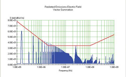
The Radiated Emissions graph is a plot of typical results from the program’s calculations. It shows predicted radiated emissions (blue) compared to the radiated emissions limit (red). Image courtesy EMI Software LLC.
But aren’t there tools to help product and system designers overcome EMI problems? Well, yes: Tools are available from both large developers—such as ANSYS, which offers suites of software to address EMI in the context of other issues—and from small companies launched specifically to address this area. Be warned, though, there is confusion and controversy even in this area. “People will fail a test and hop online to search for EMI software,” says Newson, who notes that “products are being called EMI analysis tools that are not.”
Dr. Howard Johnson of Signal Consulting Inc., an inventor, author and noted expert in high-speed digital design, still stands by the statement he made in 1998 in EDN magazine: “Real, live EMI problems are much too complex for even the best software tools. As much as I wish the situation were untrue, at this point the best tool is still experience,” he wrote.
Johnson told Desktop Engineering that the comment “is as true today as it was then. Real EMI problems are still too complex for even the best software tools to accurately predict exact EMI levels.”
He does point to one major change, the fact that there are now two groups of tools available—one from Dr. Todd Hubing at Clemson University, and another from Archambeault that is marketed through Moss Bay.
“They are both expert system-type tools. That is, they give you advice about best practices, and they give you general ideas about things,” Johnson says. “But they do not attempt to predict exact EMI levels; that’s the thing that’s still too difficult to do.”
Newson says he began software development in 1995 precisely because “there were no good analysis tools for predicting outcomes.” He says EMI problems resulting from ICs, PCBs, and enclosures, while quite difficult to model accurately, “account for fewer EMI failures and are generally easier to identify and correct.” And although there is “still no tool that can adequately model a complete electronic system,” Newson notes that “what can be accurately modeled is the circuitry and cabling ... which is the cause of most EMI test failures.” This, he says, is the strength of EMI Analyst, a tool he offers through his software company, EMI Software LLC.
EMI Analyst combines all four facets of EMI analysis through four integrated programs:
- the Conducted Emissions Analyst program calculates the amplitude of radio frequency current and voltage conducted on electric circuit wiring;
- the Conducted Susceptibility Analyst calculates voltage and current amplitude induced in circuits by voltage or current waveforms that are injected on the conductors to which the circuits are connected;
- the Radiated Emissions Analyst calculates the amplitude of electric and magnetic fields radiated from conductors carrying radio frequency current; and
- Radiated Susceptibility calculates voltage and current induced in circuits when an electromagnetic field strikes the conductors to which the circuits are connected.
Each provides templates that model waveforms, filtering and conductors using values designers fill in on pages that come up on screen. Then, when the user hits the calculate button and the software overlays the limit line, he or she “can do apples-to-apples comparison,” explains Newson. “The software becomes a learning tool.”
For instance, Newson offers, “resonance in the filter components is a common problem, so the designer can look at every point in the circuit to see which filter components are working and which are interacting.”
An updated release of this software, which should be out by the time you read this, provides more sophisticated modeling of noise sources, representing subtle characteristics of differential and common mode noise to determine what effects they have on emissions and susceptibility.
Markus Kopp, product manager, Electronics at ANSYS Inc., says many people would be surprised to learn how far simulation software has come in just the past five years. While he agrees that EMI issues can be “very complex,” and says that a single software package cannot predict all EMI and sources thereof, he also notes that for engineers—who tend to look at problems in a methodical way—such tools can still be very helpful. “If you judiciously use the available ANSYS tools, you can get clear insight into the causes of EMI issues and problems that are likely to arise,” he says.
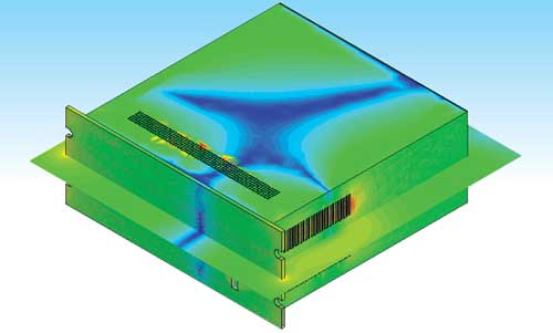
Ansoft Designer 6.0 enables visualization of the electrical field that exists at a particular frequency on a PC enclosure. You can see the fields on the “cut-plane” that bisects the model; a PCB inside is the source. Image courtesy ANSYS.
Last summer, ANSYS announced the release of Ansoft Designer 6.0 with new Solver on Demand technology, which promised to enable designers of electronic packages and PCBs to quickly and accurately analyze signal integrity, power integrity and EMI problems from a single schematic- and layout-based environment. Kopp explains that Designer in and of itself does not solve EMI type problems; it is part of ANSYS’s methodology and works together with other ANSYS tools, specifically with SIwave (for board analysis) or HFSS (that is, High Frequency Structure Simulator for electromagnetic field simulation of full 3D enclosures). Briefly, the steps—beginning with PCB analysis—that are involved in using these tools together are:
1. Import the PCB layout into SIwave
2. Perform analysis of PCB in SIwave
3. Dynamically link SIwave results into Ansoft Designer
4. Attach drivers and receivers in Designer to linked SIwave model
5. Perform a time/frequency domain analysis of entire system in Designer
6. Push voltage/excitation levels back to SIwave
7. Dynamically link the SIwave model into HFSS
8.Solve the full system in HFSS (Those not doing PCB design would skip the first six steps.)
Getting Educated
According to Archambeault, there’s really no one EMI modeling tool that the average engineer can use effectively. And a major stumbling block is that designers often don’t know how to set up their problems correctly.
“One of my jobs is full-wave computer modeling,” he says. “In one project, it took a week-and-a-half to predict how much extra shielding was needed. You really need an engineer with a solid EM background.”
The question remains, then: How do you get this background without traveling the rocky road characterized by the bad burns and failures that Archambeault and Newson describe?
There are many options, including training and consulting from people like Archambeault, Johnson, Newson and others. Archambeault’s books can be a good starting point, and he will bring his courses to any location. Johnson recommends sending a bright, ambitious engineer in your company for at least one in-person consultation, then arranging for phone or email followup as needed. Newson offers video-enhanced, Internet-based assistance through GoToMeeting.
The Clemson Vehicular Electronics Laboratory (CVEL) and the Missouri University of Science and Technology have collaborated to offer Hubing’s “EMC Principles” course (36 videotaped lectures) on DVD. This is one of the classes that Missouri S&T offers for its EMC Certificate, which the university awards for the successful completion of two video non-credit courses. Others are available as well. In addition, Clemson offers a number of short courses—on campus, at locations around the world, and by arrangement as in-house presentations at client locations.
A number of associations also offer help: The IEEE’s EMC Society has chapters all around the world, and holds an annual conference. The Electrostatic Discharge Association, Applied Computational Electromagnetics Society (ACES), and Electrostatics Society of America likewise offer publications and training through annual meetings.
First Rule for Sourcing
Archambeault recommends that designers who built products incorporating electronics “look for the FCC or CE mark” on the electronic equipment, “and make sure it’s been tested in the environment in which you plan to use it.”
To emphasize the importance of environment-specific testing, he tells about a recent project involving a CE-marked, solid-state disk drive that was purchased for use within a large system. Once the drive had been placed in a rack with about 35 additional pieces of equipment and all the components were tested, the disk drive failed. “The vendor showed us the results of emissions testing—which was fine. But putting all those pieces together caused a problem.”
Archambeault points out that the U.S. has FCC rules for emissions—but does not have immunity requirements.
Barbara G. Goode served as editor-in-chief for Sensors magazine for nine years, and currently holds the same position at BioOptics World, which covers optics and photonics for life science applications. Contact her via [email protected].
For More Info
ANSYS Inc.
Applied Computational Electromagnetics Society
Dr. Bruce Archambeault
Clemson Vehicular Electronics Laboratory
Electrostatic Discharge Association
Electrostatics Society of America
EMC Journal
EMI Software LLC
IEEE EMC Society
International Electrotechnical Commission
Missouri University of Science and Technology’s Center for
Electro Magnetic Compatibility
Moss Bay EDA
Newson Consulting Inc.
Signal Consulting Inc.
Subscribe to our FREE magazine, FREE email newsletters or both!
Latest News
About the Author
DE’s editors contribute news and new product announcements to Digital Engineering.
Press releases may be sent to them via [email protected].


