

Latest News
June 21, 2010
By Yuya Ando, Software Cradle
Properly designing a heating, ventilation, and air conditioning (HVAC) system to consistently provide a comfortable environment for human occupants is a challenging fluid/thermal problem. High customer satisfaction means ensuring proper temperatures and air flows are produced at all points in the operating space and not just for specific design conditions.
Despite advancements in computational fluid dynamics (CFD) as a design tool, a critical piece of the HVAC design puzzle has still been missing. This missing link is the skin temperature of the human subjects themselves. Failure to calculate the temperature of the human subjects in the HVAC environment is akin to merely calculating the temperature and heat transfer coefficient around a large mass in an oven and assuming the mass will be properly baked. The analogous problem becomes even more complicated when multiple masses (i.e. many people) are involved.
From a simulation perspective, the primary challenge is accurately modeling the human body. The human body is an extremely complicated fluid/thermal system. It is physically complex (skin, tissues, blood flow) and it also comes in many different shapes and sizes. Heretofore, commercial CFD codes have not included a heat transfer model for the human body despite it being the critical piece of the HVAC design puzzle. Recently, third-party heat transfer software products have started to include human body models. However, these software products require separately coupling the airflow around the body with the human body internal heat transfer calculations in order to pass temperature and convection coefficient information between the CFD code and the heat transfer software. The ideal situation is to embed the human body heat transfer model within the CFD code. This fully couples the body temperature calculations with the calculations for the surrounding flow field.
Professor Shin-ichi Tanabe at the Waseda University in Tokyo, Japan, has worked to develop an accurate thermoregulation model of the human body. This model is called JOS (JOint System Thermoregulation Model). To meet the needs of the HVAC simulation market, Software Cradle Co., Ltd., developer of SC/Tetra CFD software, worked with professor Tanabe to integrate JOS into its recently released SC/Tetra Version 7 CFD software product. The integration of JOS within SC/Tetra is comprised of three parts.
1. JOS computes the temperature of the human body. JOS is a physical model based on the heat balance equations for divided body segments. JOS inputs include age, sex, basal metabolic rate, and fat rate. JOS considers thermal conductance between tissues, the detailed vascular system, and the thermoregulatory system consisting of perspiration, vasomotion, shivering heat production, and arterio-venous anatomies (AVA).
2. CFD is used to compute the temperature and air velocities in the fluid environment. The fluid domain is modeled in a traditional manner. Grid meshing is only required in the fluid domain and not within the human body/bodies.
3. Boundary conditions couple JOS to the fluid domain. Energy is passed between the human body thermoregulation model and the fluid CFD environment through the body skin. Thermal resistance due to clothing, and water vapor concentration from perspiration diffusing into the air at the skin surface form the boundary conditions for the CFD calculations. The air temperature and the water vapor at the skin surface are the boundary conditions for the thermoregulation model.
The JOS Model
JOS models the human body by dividing it into 17 body segments. Individual body segments consist of a core layer and a skin layer. In the center of the core layer are both an artery blood pool and a vein blood pool used for modeling the vascular system. In addition, a superficial vein blood pool is modeled in the skin layer of limb segments.
The blood pools for each segment constitute the vascular system around the heart. Pathways flow from the heart to the head, chest, back, hands and feet. AVA accounts for changes in blood flow due to changes in the ambient environment. AVA is a vessel between the artery blood pool and the superficial vein blood pool to model the change in blood flow. For example, in a hot environment AVA is opened, which promotes additional blood flow and increased heat release from the skin surface.
Heat exchange occurs within each body segment and includes heat production (except at the extremities). Heat loss at the skin surface, by convection and radiation (sensible heat loss), and evaporation (latent heat loss) are the boundary conditions for the segment heat transfer model. Sensible heat loss accounts for the thermal resistance caused by different types of clothing. Heat is conducted through the tissues and considers transfer between the core layer and blood vessels, core layer and skin, and countercurrent heat exchange between the arteries and veins. Conduction heat transfer between segments is negligible compared to heat transfer from the blood flow. Heat production within each segment by basal metabolism occurs in the core and skin layers.
Physiological factors of the human body must be considered within the thermoregulation model calculations. These include thermal conductance between tissues, thermal capacity of tissues, basal metabolic rate, and the basal blood flow rate. These factors are largely a function of the size of the body/bodies, age, sex, and percent body fat. Body size is determined from the CFD calculation mesh. While no CFD calculation mesh is required within the body, the boundary cells around the body define the surface area and consequent size of the body.
Using JOS within SC/Tetra
As general purpose CFD software, SC/Tetra can import HVAC geometry in a variety of standard formats. Using SC/Tetras intuitive navigational screens, its pre-processor can import either model data (e.g. STL, DXF format, and others) or a surface mesh (e.g. NASTRAN file) to define the system geometry. Once the system geometry has been specified, SC/Tetras mesh diagnostics, geometry repair capabilities, and grid generator can be used to generate a volume mesh.
The input process continues by specifying boundary conditions. SC/Tetra provides an interface to input JOS specific data. Inputs consist of age, sex, body fat rate, and metabolic rate. Body surface areas must be registered as either being in contact with air or with a solid surface. Additional commands are used to define computational requirements such as outputs, time steps, number of CFD calculations per loop, and convergence criteria. Outputs can be viewed numerically or graphically using SC/Tetras post processor.
Sample Results
Sample graphical output from SC/Tetra and JOS shows how a particular automotive HVAC system performs. The velocity vector plot shows a typical CFD output for the air velocities and temperatures. This plot shows where the air goes, but does not translate its effect on how the occupants actually feel when they are also subject to radiation from the sun, conduction where their bodies contact the seat, and their individual physiological make-up. JOS value is that it calculates the skin temperature distribution for each occupant. This more properly reflects how the person actually feels. The skin temperature computation accounts for all the factors affecting human body heat transfer. Higher skin temperatures are experienced where the solar load is high, airflow is low, and at physical points of contact.
HVAC engineers use the calculated skin temperatures at critical regions on the body to generate a comfort index that quantifies the effectiveness of a particular HVAC system design. The comfort index can be used to evaluate design modifications. It can also be used to evaluate how the design will perform at different operating conditions (e.g. different solar loads or external temperatures) and for different configurations (e.g. more people in the space).
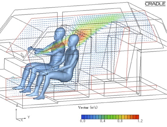
CFD graphic displaying air flow in an automobile interior.
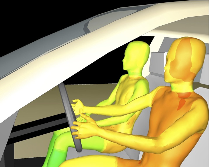
Temperature of occupants inside vehicle.
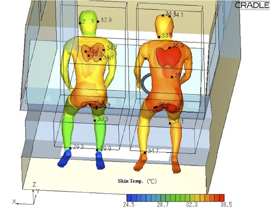
Skin temperature distribution at contact interface.
The integration of JOS within SC/Tetra CFD software enables HVAC engineers to take a step toward improving their HVAC system designs and to ensure that the designs will operate effectively throughout the specification envelope. Someday, when HVAC systems are designed using these computations tools, people should no longer need to think about having to bring a sweater to stay warm at a large indoor event when its 95°F outside.
Subscribe to our FREE magazine, FREE email newsletters or both!
Latest News
About the Author
DE’s editors contribute news and new product announcements to Digital Engineering.
Press releases may be sent to them via [email protected].


