

June 1, 2005
By Matt Lombard
For those times when you really need a hybrid modeler, the chances are pretty good that you already have one.
We hear the word “hybrid” used a lot these days, and not just in the automotive world. It’s easy to understand the hybrid nature of an automobile with two sources of power, but what does the term “hybrid modeling” actually mean to people who do everyday 3D MCAD work?
That depends. If you spell “hybrid” with a capital “H,” it can be just a marketing buzzword, meant to make companies ready to spend money on new MCAD software believe that a particular vendor has invented the practice of working in both solids and surfaces. If you spell “hybrid” with a lowercase “h,” it is the practice of working in both solids and surfaces.
Hybrid modeling is not a new concept. Working sometimes in surfaces and sometimes in solids on the same model is a practice that has been around as long as solid modeling itself. Solids are really just surfaces that follow a set of rules enforced by the modeling software, such as maintaining a watertight set of surfaces, without gaps or overlaps, and differentiating the inside of the solid from the outside. The modeling software is doing a lot of automated tasks behind the scenes to make all this happen, all (or most) of which can be done manually in hybrid modelers.
This article deals with the hybrid modeling issue in MCAD-neutral terms, aside from the examples, which are in SolidWorks 2005. There are more than a dozen commercial MCAD and CAM products that to some extent could be called “hybrid” modelers. This is not the article to compare the various commercial products. Rather, here I will deal with the relative strengths and weaknesses of solids and surfaces techniques, and offer some guidelines for when one or the other might be most beneficial.
The main advantage of solid modeling over surface modeling is that for most types of prismatic part work, solids are much faster because of the automated tasks the modeling software does behind the scenes. To demonstrate, let’s take the example of a simple plate (see Figure 1, below).
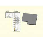 |
| Figure 1: Surface Features versus Solid Features: Total regeneration time = 0.15 seconds for surfaces and 0.05 seconds for solids. Click image to enlarge. |
1. Sketch a shape to size
2. Extrude the sketch to depth
What is really going on behind the scenes is this:
1. Create sketch elements
2. Create a surface perpendicular to the sketch plane of each sketch element (a total of seven times for this example)
3. Create two planar end cap surfaces-at this point there are six independent surface bodies
4. “Trim and knit,” make sure that there are no gaps or overlaps, and merge coincident edges of adjacent faces into the same edge; all faces are now part of a single surface body
7. Adjust face normals so they all point toward the outside of the “solid”
For this type of modeling, clearly, solids would be the preferred method rather than manually doing all the surfacing functions.
Other advantages solids hold over surfaces include the ability to get mass properties and section views that are easier to interpret.
Advantage: Surfaces Over Solids
Likewise, surface modeling has two principal advantages over solid modeling. First is in the type of modeling when shapes must be constructed face by face. This is often associated either with complex shapes or with imported models that must be rebuilt or repaired face by face. The second main advantage can come in terms of efficiency.
In the example in Figure 1 (above), the solid was more efficient, but that is not always the situation. Let’s look at the next example, Figure 2 (below), again using SolidWorks 2005 as the modeler.
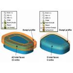 |
| Figure 2: Extra surfaces created by a Swept Cut versus the efficiency of a Cut with Surface. Solid cut (left) = 0.37 seconds; Cut with Surface (right) = 0.31 seconds. |
The swept solid cut technique is a bad habit that a lot of users (including myself) have fallen into. This is a solid technique that is better handled using surfaces to manipulate the solid-hence a hybrid technique. Notice that the swept profile (shown in red) has five elements-four straight lines and one elliptical. Only the elliptical element will be used in the final shape; the straight lines are just there because “that’s the way solid modelers work.” It’s extra work to create these elements, and often they are not set up to flow well with changes to the model, so they tend to create a lot of rebuild errors.
If the sweep path (the edge going around the flat face of the part) has eight segments and the profile sketch has five elements, then the sweep creates a total of 8 x 5 = 40 faces, 32 of which are extra. The extra faces don’t have any function in the finished shape. This also requires the knitting of an unnecessary temporary solid body.
The same level of inefficiency exists whether it is a solid Swept Cut, a Thickened Surface Cut, or a Cut up to Surface. In fact, no solid function can avoid this inefficiency. (A Face Fillet with Hold Lines could come close, but would not give an elliptical face.)
On the other hand, a surface sweep only creates eight faces, all of which are used in the finished shape. The edge is cut away using Cut with Surface, and in effect is just trimming the faces of the solid, replacing the swept elliptical “fillet.”
The result is a model that is more robust through changes, rebuilds faster, and has added another technique to your toolbox for getting work done.
With the solids versus surfaces question in mind, remember that there are two types of efficiency to consider when determining how you should approach building a part. The first is modeling efficiency, or how long it takes you to create the model. The second is rebuild efficiency, or how long the software takes to regenerate the features.
Solids generally take you less time to create, but they can take more time to regenerate when they create many redundant faces. If you rarely make changes, then maybe modeling efficiency should be your predominant concern, but most of my modeling work follows the rule “build once, change eight times.”
The behind the scenes modeling tasks are most evident when you work with a neutral format such as IGES. IGES data is not solid by nature. It’s just a collection of mathematical definitions of faces and other geometrical entities. It could be read into two different modelers or even into a single modeler with different settings and give the same geometry which in one case is treated like a solid body and in another case is treated like a surface body.
If you are the type of MCAD user who models exclusively with solids even though you have hybrid-capable software, broaden your horizons a little and start asking yourself, “is this feature overkill? Should this be done with surfaces instead?”
Clearly, there are good reasons for using solids. However, it is also clear that surfaces have uses that are not limited to the complex shapes of consumer product design. The tools to work in both surfaces and solids certainly exist, but many users don’t seem to be completely aware of the benefits of mixing their MCAD metaphors.
To conclude, you may be sitting on more horsepower than you imagined. You may not find the word “hybrid” in your modeling software’s help file, or in any of its marketing or training materials, but that hybrid dual source of power is likely there if you are using a popular mainstream commercial MCAD product. Just because you don’t create sexy consumer products doesn’t mean you can’t benefit from the added control and efficiency of surfacing techniques.
Matt Lombard is an independent consultant with expertise in SolidWorks and CAD administrative services. Matt is also a volunteer leader of two SolidWorks user groups in Virginia. Send your comments to Matt via e-mail c/o DE‘s Editors.
Little Known Tools Make It Easier
Let’s go one step further down the hybrid path. When you import a model that has extra features that you would like to remove-such as fillets on an undrafted plastic part, the wrong size bend radii on a sheet metal part, or extra mounting holes in a plate-using the typical solid feature fill-ins and cut-offs is not necessarily the best or even the easiest approach. A decent hybrid modeler such as SolidWorks may have some hidden hybrid tools that you don’t know about that would make dealing with these situations easier. Here’s some to try out next time you’re faced with this sort of problem.—ML
Delete Face-Will remove a face from a solid or surface body. When you remove the face of a solid, the solid becomes a surface body if the Delete Face tool does not immediately patch it. (See Figure 3, below.)
 |
| Figure 3: A model before and after use of the Delete Face tool with the Patch Hole option. Click image to enlarge. |
Delete Hole and Untrim—These tools can reveal underlying NURBS surfaces to seamlessly patch over a hole even for faces with complex curvature.
Fill Surface—This surface function can merge itself into the surrounding solid.
Imported Geometry—This allows you to bring an imported solid or surface model into an existing model. (Note: This is not the Open dialog; this is a separate feature.)
Insert Part—Allows you to bring another existing SolidWorks part with its solid and/or surface bodies into the existing model.
Move/Rotate Face—This allows editing of both solid and surface models, whether native or imported. Fantastic for adding draft or making size edits to “dumb” imported models. This can also be used to add or remove material.
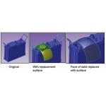
Replace Face—Allows you to replace faces of a solid with a surface body. One of the best things about this is that it can add and remove material simultaneously in a single function.
(Even If They Don’t Mention It)
Who What
Ashlar-Vellum Argon, Cobalt, Xeon
Cimatron Cimatron E
CNC Software Mastercam Solids
CoCreate Designer Modeling
Delcam PowerShape
ImpactXoft IxSPeeD
IMSI TurboCAD
Kubotek KeyCreator (CADKEY)
Missler TopSolid
PTC Pro/Engineer
Schott Systeme Pictures by PC
SolidWorks Corp. SolidWorks
Think3 thinkdesign
UGS Corp. NX
UGS Corp. Solid Edge
Vero Software VISI-Modelling
VX Corp. VX CAD/CAM
Subscribe to our FREE magazine, FREE email newsletters or both!
About the Author
DE’s editors contribute news and new product announcements to Digital Engineering.
Press releases may be sent to them via [email protected].


