Hybrid System Simulation Using LabVIEW
Part 2: Improving the development process using NI simulation tools in combination with MCAD tools and others, such as Simulink.


Latest News
May 1, 2008
By Javier Gutierrez
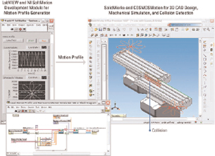 This diagram shows a LabVIEW motion profile being sent to a model created in SolidWorks. |
The engineering design process often features simulation to analyze a system’s behavior for effective controller design. Because of this, the simulation not only involves the system under study, but also the actuator to verify whether design specifications are met. With this in mind, moving directly from simulation to real-world, real-time implementation can further speed up the design process.
Rapid control prototyping (RCP) and hardware-in-the-loop (HIL) testing are examples of applications for which simulation models run on real-time hardware. Let’s take a look at some tools and techniques to model systems and controllers, ways to deploy them to real-world platforms, and explore how to deploy models when the design process involves different tools.
To illustrate the methods, processes, and tools used in simulation, let’s look at the development of a controller to modify the performance of a well-known academic example, the spring-mass-damper system. The system consists of a mass attached to a spring that is, in turn, attached to a fixed point such as an actuator that provides a force on the mass. The whole system moves horizontally and, as a result of the friction between the mass and the floor, some energy is lost. Depending on the complexity of their systems, engineers might make some simplifications like not considering air friction, assuming that temperature has no effect on the damping value, and determining that the spring shows a perfectly linear behavior.
If a system has a unique description, how can it have several representations? Furthermore, how are these representations helpful in the engineering design process?
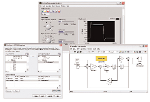 Adding LabVIEW user interface to model created using The MathWorks Simulink software. |
Simulation Abstraction
Before running a system simulation, engineers have to ask two questions: “How complex should my model be?” and “Which behaviors am I interested in studying?” Answers to these questions are critical because modeling can be a lengthy task and the benefits of a higher-fidelity simulation might not outweigh the effort involved. In this example, engineers might be tempted to build a model using finite element analysis (FEA). In that case, they model the mass, the spring, the connections, and so on with a very high fidelity. Engineers can analyze effects such as elasticity in the spring or friction changes between mass and floor as heat dissipates, but this information probably does not increase their understanding of the process or significantly enhance the controller they are developing.
Each representation has its benefits and its drawbacks. Typically a more complex, higher-fidelity model better represents the behavior of the physical system, but it is much harder to model and it requires more resources to analyze it and implement it on a real-world platform. Other simulation representations use tools such as SolidWorks, which features FEA. AMESim and other tools included in Simulink from The MathWorks provide the means to model physical systems to describe mechanical, electrical, and hydraulic behaviors. Simulink and the NI LabVIEW Control Design and Simulation Module use a graphical approach, where engineers combine functional blocks to create complex systems. Another MathWorks program, MATLAB, and National Instruments’ LabVIEW MathScript (part of the LabVIEW programming language) use a text-based approach that also features function calls. The graph at the lower right shows how these different tools represent the example system.
Simulation Tools
Different methods to describe a physical system mean different tools to implement those descriptions. Typically, engineering processes require more than a single tool to cover all system approaches, so engineers often have to choose the tool that provides the most satisfactory result. But as tools are refined, so are the interfaces they offer. This leads to new, better design processes where simulations are no longer limited to a single tool and engineers can choose the right tool for the right job and mix and match tools and procedures as needed. An added benefit of combining different simulation tools is the ability of different design teams to work closely together. For example, when the tools used by the mechanical department can integrate with the tools used by the electrical department, these two teams can work together to find design errors earlier in the process.
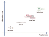 This is graph illustrates model abstractionversus software requirements. |
LabVIEW and SolidWorks
Engineers who use SolidWorks can add dynamic system simulation to FEA models with the COSMOSMotion package. FEA modeling is useful, especially for machine builders, to experiment with virtual assemblies and analyze tolerances, interferences, and so on. There are limitations, though, like how to integrate the action of external devices, such as sensors, motors, and motion controllers that might be present on the assembly.
One possible solution to this challenge is the LabVIEW graphical system design platform. Engineers can use LabVIEW and its advanced motion libraries to define the trajectory profile for the machine. This profile includes information on position, speed, and acceleration and defines the system performance and throughput. COSMOSMotion can load this profile and simulate the torque and other features that external motors should provide to achieve the specified profile. This information can then feed back to LabVIEW, where engineers can run a DC motor simulation with all the information gathered (speed, torque, time, and so on) to evaluate different motor options. This integration between LabVIEW and SolidWorks benefits the design process because engineers can dimension the motor correctly based on simulations and performance specifications. They can reduce their chances of using motors that lack the torque to meet the design criteria or that offer too much power and unnecessarily increase the cost of the machine.
LabVIEW and AMESim
AMESim, from LMS International, is a tool capable of a high level of abstraction. Engineers can define systems by pulling together icons that represent mechanical or electrical entities. Then they can build complex systems by “drawing” their schematic representations. Even when this representation offers good high-fidelity simulation, it is difficult to compile users’ models into real-time hardware platforms for RCP or HIL applications. AMESim models must be combined with other tools that are capable of running on real-time targets.
LMS recently announced the capability of users’ models created in the AMESim software to be executed in LabVIEW. By using these two tools, engineers can develop high-fidelity models in AMESim and compile them to run in LabVIEW. After compilation, the models can then be deployed to any LabVIEW Real-Time hardware targets such as PXI or NI CompactRIO hardware.
LabVIEW and Simulink
Simulink is widely used in automotive and aerospace applications. Engineers can define systems with a wide variety of libraries, but, as noted previously, software can get them only so far.
National Instruments offers the LabVIEW Simulation Interface Toolkit, which engineers can use to facilitate compilation of their models created using Simulink. And once a model can run in LabVIEW, it is ready to run on any real-time target platform compatible with LabVIEW. This opens the door to RCP and HIL applications and helps engineers move quickly and efficiently from modeling to real-world implementation. To learn more about how to use LabVIEW to execute simulation models you built using The MathWorks Simulink software, visit ni.com/hil.
Although engineering design processes feature simulation to some extent, the variety of simulation tools and the different levels of compatibility make it difficult for engineers to fully take advantage of its power. Engineers can use simulation in a broad spectrum of applications, but it is difficult, if not impossible, for a single tool to cover all the possible cases. By using LabVIEW simulation tools with other simulation products from different vendors, engineers can meet these challenges and improve their design processes.
Javier Gutierrez is a control systems engineer for National Instruments and has worked for NI for more than seven years. He now manages the Control Design and Simulation product line. Send e-mail about this article to [email protected].
Info:
LMS International
Leuven, Belgium
lmsintl.com
The MathWorks, Inc.
Natick, MA
mathworks.com
MicroNova Software and Systems
Vierkirchen, Germany
micronova.de
National Instruments
Austin, TX
ni.com
Rensselaer Polytechnic Institute (RPI)
Troy, NY
rpi.edu
SolidWorks
Concord, MA
solidworks.com
Subscribe to our FREE magazine, FREE email newsletters or both!
Latest News
About the Author
DE’s editors contribute news and new product announcements to Digital Engineering.
Press releases may be sent to them via [email protected].


