

Latest News
November 1, 2010
By Dr. Bijan Khatib-Shahidi
Editor’s note: This article has been adapted from an article that originally appeared in benchmark, a NAFEMS publication. For more information, visit nafems.org.
Despite the recent downturn in consumer demand and the serious economic challenges across industry worldwide, today’s modern automobiles have benefited from the extensive use of computer-aided engineering (CAE) to make them quiet, durable, comfortable, stable and safe. The design and release engineers, who are responsible for signing-off on the adequacy of the component, part or system that they send to manufacturing for production, have particularly benefited from modern finite element analysis (FEA) and computational fluid dynamics (CFD) software and analysis. Their colleagues in CAE organizations conduct the analysis to better the design for the public in general. I also need to mention that in some smaller organizations, the role of the design and CAE engineer is the same, and the same engineer does both the analysis, design and release.
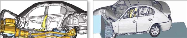 Fig. 1 and 2: The crash management system is designed and maintained during the crash scenario, including the crumple zone areas in the front and rear. Images courtesy of BMW. |
However, that does not take anything away from the discussion on the benefits that CAE provides. In my recent role as a vehicle CAE manager at a major automotive original equipment manufacturer (OEM), I experienced and watched the growth of FEA and CFD, in both capability and utilization, on engineering applications and design.
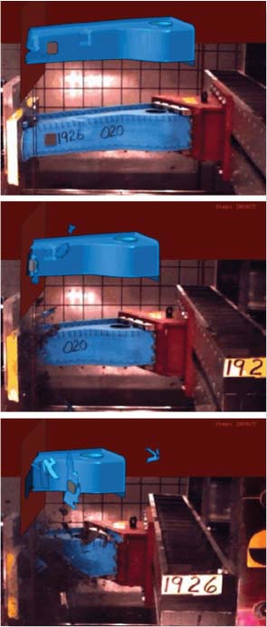 Fig. 3: The rail crush example is run in CZone for Abaqus, which is an add-on product to Abaqus/Explicit. Image courtesy of Engenuity, Ltd. |
Using FEA and CFD, our team was able to create full-vehicle model representations of cars and trucks that included many parts. We swapped different sized tires, suspensions, multiple powertrains, and chassis systems to represent a variety of vehicle configurations. We could represent these models as if they were real prototypes. They included acoustic representations to measure noise predictions. We added sub-system representations of multiple engine/ transmissions, axles and drivelines, different trim levels, and excited them with various load conditions such as road profiles, wind loads (winter and summer modelling, and different yaw angles), engine loads, driveline imperfection scenarios, and so on.
New capabilities, such as one from Abaqus software, allowed rolling tire capabilities and sub-structuring, as well as the ability to switch from implicit to explicit analysis and vice versa to mimic road noise, vibration and harshness (NVH), and durability analysis.
I need to reiterate that these models enabled our designers and development engineers to identify, early in the design phase, any necessary “fixes” that were required to achieve consumer and regulatory targets, and also to avoid back-breaking vehicle recalls. This avoided (for the most part) the building of physical prototyping, which were then only used for validation and comparison. Such CAE simulations also enabled the teams to provide scientific cost forecasts used to report to the senior management before they agreed to sign off on any production go-ahead.
Improving Efficiency
There is huge competition among the 100+ car industries across the globe, which is due in no small part to the convergence of design and styling, engineering content, and the never-ending demand from the costumers to have more and more included in the cars they purchase. Because of this, the companies face major economic pressures on a daily basis. In order for them to stay afloat, these manufacturing companies are more focused than ever on improving engineering efficiency, lowering development costs, and accelerating product innovation faster than the competition next door.
I have seen FEA/CFD and other simulation solutions playing an increasingly prominent role in helping every industry to design better, optimize more often, and reuse the existing design in a different platform (with the new morphing technologies) to cut costs and to become as competitive as possible. There is no other way. The convergences in the economic conditions have made this problem universal, making it more difficult to build distinctive products. This situation is no longer unique to the automotive industry.
Any industry that is in the business of manufacturing can benefit from CAE. Nowadays, every country is building cars, airplanes, washing machines and food processors, so it is necessary to be design distinctive, efficient, and fast to market. CAE tools can play a prominent role in achieving most of these goals.
Nonlinear FEA Closer to Reality
Advances in commercial FEA technology are enabling engineers to get closer than ever to simulating realistic behavior through the inclusion of nonlinear effects in processes such as rolling tires, and in materials such as rubber, plastics, and exotic metals and composites. These materials are used in design along with standard metals such as steel or aluminium. The nonlinear FEA capabilities dramatically improve the accuracy of FEA results when they are compared to linear simulations, and for instance, in noise and vibration stress and/or durability, thermal comfort and safety, and crash and blast models. Head-on and offset car impact are all represented as detailed models to fulfil the safety and regulatory missions with the simulation.
For example, consider the complex non-linear crash analysis computations done by BMW. The crash management system is well designed and maintained during the crash scenario, including the crumple zone areas in the front and rear, as demonstrated in Figures 1 and 2. Inclusion of various “non-linearities,” such as composite material behavior and the loads in the simulation models make the results come closer than ever to the physical reality. Figure 3 represents the non-linear crash simulation that is done on a composite structural member subjected to offset axial crushing.
The complex composite analysis results have been compared to the test set up in the lab with great accuracy. The rail crush example (Figure 3) is run in CZone for Abaqus, which is an add-on product to Abaqus/Explicit. Modelling conditions such as variability on what percentage of welds could be missing in the manufacturing process during the build process are important. Adding the stochastic and probability modelling on top of the aforementioned non-linearity makes the analysis more valuable than ever.
Hardware Powers Increasingly Sophisticated Software
The computer hardware on which advanced analyses—such as full crash analysis and NVH, thermal comfort, CFD, safety or blast analysis, are run —has also come a long way in recent years, and will become even more powerful in the future. An additional benefit of less expensive, parallel and faster computing is that the design of experiments (DOE), optimization, stochastic and probability analysis can now become a natural extension of the engineer’s analysis and modelling process.
In addition to the computing power, the capabilities available to the CAE engineer have increased in the last few years in tandem with the improvements in the parallelization of algorithms in FEA, CFD and multiphysics software, in combination with other enhancements, such as accurate sub-structuring that allows the models to get even larger in size and content. These refinements are allowing engineers to build ever more realistic FEA/ CFD models with increasingly finer and finer meshes.
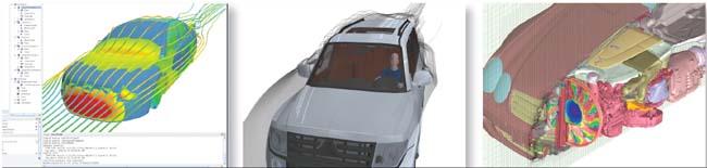 Fig. 4, 5 and 6: Examples of what can be done with software. You transfer results such as the pressure fluctuations to a structural software, such as Simulia’s Abaqus, NASTRAN or acoustic software such as ACTRAN, for further analysis, such as noise predictions inside the cabin of a car. Images courtesy CD-adapco. |
One other noteworthy remark is that not only have software and hardware come a long way from its power of representation in multi-physics, it is also getting simpler to use. A case in point is the utilization of pre-processors such as Hypermesh (From Altair Engineering), ANSA (from Beta CAE), Abaqus CAE (From Simulia) and the Mesh Wrapping capability in STARCCM+ (CD-adapco) to create complex models quickly, and even to get them to communicate and pass results between different software packages. All in all, it is allowing the engineer to learn and adapt quickly to changing economic conditions.
Register for the 2010 North American Virtual Conference NAFEMS, the only worldwide independent association dedicated to engineering simulation and the people who use it, has announced the keynote speakers and presentation lineup for its upcoming NAFEMS North American 2010 Virtual Conference: 2020 Vision of Engineering Analysis and Simulation on Nov. 15-16, 2010. This pioneering online event, containing most of the elements of a traditional conference, but without the costs of travel and accommodations for the attendees, will feature more than 20 live presentations in the auditorium and numerous major simulation technology vendors in the exhibition hall. |
I remember the first safety model I built had about 10,000 elements to represent a C or D size sedan in the late ’80s. That safety model, although helpful in designing the trigger mechanisms for better crash repeatability and axial load management, missed the crush distance by quite a lot when the model’s crush distance was compared to its physical prototype counterpart. That was due to the limitation of the computing power that existed within the Cray XMP, one of the most powerful computers that existed at the time. We could only get qualitative results to fine tune a model and help with the component detail design to strategically place the front rail trigger mechanisms and optimize the crush absorption.
However, we could not sign off on a design with such crash models or even totally eliminate a prototype. Today, because computers are more powerful and available, one can do wonders with non-linear analysis even on household computers.
Crash models with 2 million elements or more are common nowadays. The crash and safety engineers at Toyota have reported that they have created models reaching more than 14 million elements, with elements as small as 1 to 2 mm in size. These types of models include so much detail that they can then be used to decide, for example, where the proper location is for airbag sensors and what amount of deceleration should trigger them. CAE models provide a great deal of detailed information, which in turn improves the quality of designs, ensuring better results decade after decade. This results in a general reduction in the need for expensive physical prototypes, which cost hundreds of thousands of dollars and are destroyed in fraction of a second.
The NVH linear models of the ’90s era only ever had around 100,000 linear representations with a number of super element structures to predict noise levels at the 80 to 100Hz frequency coverage. These models are now represented by more than 2 million elements in a single shot, including rolling tires and the frequency coverage of 300 to 450Hz, thanks in part to software such as sub-structuring and automated multi-level sub-structuring (AMLS), as well as the availability of inexpensive powerful computers available to the greater public. These types of models can help designers and engineers to place “Quiet Steel,” multi-layer laminates in strategic locations, in the cars and trucks to quiet down the noisy panels. The models can also help in the realization of the type of trim materials, such as carpet and plastics, which can be used. This trim modelling capability was not possible or readily available in the ’80s and early ’90s.
On the CFD front
In previous times, some of our CFD engineers would take two to three weeks to create 2.5 million finite volume cells in an aerodynamics section, which would take a few days to run on multiple CPUs. The results would vary by about 0.020 when we compared the coefficient of drag prediction to the wind tunnel tests. A higher number of cells would provide a better prediction, but it would take even longer for the analysis to complete. For this reason, engineers often preferred to go to the wind tunnel for quicker results as well as a more accurate representation.
These days, it is extremely easy to create CFD models. I recently created an external aero model of a full vehicle representation with the inclusion of the occupants, including the windows open condition, with about 30 million cells. This took only about three hours to complete, and a few hours later (in the same day I might add) I would get the results back with accurate aero predictions, and certainly within the variability range of a shape and content. Using CCM+ for model creation is very easy; all one needs is CAD data that is fairly air- and watertight. CCM+ is also forgiving if there are few holes, which it can repair after one takes it to its pre-processing mode. Once in there, you can fill the unwanted holes and move on to wrap the surface, and then with a few clicks you can create an “automated” volume mesh. It is relatively straightforward, and as such the learning curve is very fast even for first time CCM+ users, although obviously it helps if one has some background in the theory and its application.
I could not show my analysis results and pictures for confidentiality reasons, but instead I have included some publicly released pictures from CD-adapco. Figures 4, 5 and 6 are examples of what one can do with their software and even in some more advanced applications. One can transfer results such as the pressure fluctuations to a structural software, such as Simulia’s Abaqus, NASTRAN or acoustic software such as ACTRAN, for further analysis, such as noise predictions inside the cabin of a car due to structural vibrations from that of the dynamic fluid pressure induced upon it.
Blast and Explosion
Another extension of the CAE capabilities is in the area of safety design for blast and explosion mitigation. This is a technology that combines the Lagrangian mesh that is traditionally used for typical crash modelling and analysis with that of the Eulerian mesh that is used to represent the blast of explosives that travels through the air or ground, and delivers a supersonic shock to the vehicle in question. The aim is to design a vehicle that is safe under the blast explosion through analysis and modelling. In some sense, one can think of it as the fluid-solid interaction (FSI) of the air blast and that of the vehicle that gets the shock through the fluid. Once again, this type of analysis requires a great deal of computer horsepower because the models can contain very large amounts of nodes and elements.
This type of analysis can become even more complex when one adds erosion, regularization and complex tri-axiality failure criteria on elements that erode or blast away, which could easily bring models upward of 15 million elements for blast type applications.
Automotive Advances Benefit Other Industries
The automotive industry is certainly one of the major staging grounds for large-scale FEA/CFD in terms of degrees of freedom. The use of vehicle durability, NVH and safety analyses have grown tenfold in the last decade, with enabling tools such as sub-structuring on calculating modal presentation. There are also several attempts going on to use MDO (multi-disciplinary optimization) analysis among these attributes.
We have come to the realization that the knowledge and experience gained in the automotive industry can become quite beneficial in other industries as well. The CAE engineers in the automotive industry have been eager to share their results and spread the success and the news of these capabilities at regional and world seminars and conferences. So the “lessons learned” in automotive simulation capability are feeding directly into heavy vehicle, military, defence, off-road, mining, aerospace and shipbuilding engineering.
Newer industries, such as life sciences, are learning that the design challenges they face in noise and vibration control of devices and machinery, such as the breathing apparatus design that needs to be “whisper quiet” during the patient’s utilization, can also benefit from the CFD and NVH know-how that automotive CAE engineers can provide. We are also likely to see increased knowledge transfer to medical, pharmaceutical, and other industries.
A Look Ahead
I see two new frontiers. First, the explicit FEA methods that have become part of crash/safety and blast and penetration simulations in recent decades will be increasingly applied to noise and vibration applications, and obviously in blast and mitigation. This will result in an increased demand for even faster computing hardware and better integration of implicit and explicit FEA techniques to help design the lighter-weight, efficient, yet comfortable vehicles of tomorrow. Software that communicates and transfers implicit and explicit data seamlessly is well-positioned for such challenges.
I also see that it is necessary to better integrate FEA and CFD, whether this is used to couple wind loads to vehicle structure, take thermal fluid and map it to the structural surface, or to help the engineers predict the fuel sloshing noise under braking and acceleration in automobiles. Once again, the software that has this capability, or even unified software that offers both FEA and CFD, is in a better marketing position than those who do not have such capabilities built-in.
Secondly is the advent of isogeometric analysis. A technique using NURBS and T-Splines as a basis for construction of element shape functions is currently being championed by professor Tom Hughes at the University of Texas at Austin. It is a new way of thinking about how finite elements will be created or modified in the future, or at least as an element selection option. This is a tremendous way to seek better accuracy to compute stresses, velocities, pressures and buckling loads. This technique even has promise in automotive applications to overcome the limitations of modal contents in noise and vibration analysis as well as perhaps more accurate computations gained in fluid dynamics.
Those companies willing and able to continue investing more in realistic simulation technology and appropriate staff will certainly benefit as they develop the next generation of “green” products. The engineers who excel in using advanced CAE simulation technology and apply it to products will be in high demand, not only in the automotive industry but as innovation leaders who will be able to apply their knowledge about the benefits of FEA/CFD applications across many other industries as well.
Dr. Bijan Khatib-Shahidi, principal consultant, Engineering Products, Inc., has worked with major manufacturers for 20 years. Contact him via [email protected].
Subscribe to our FREE magazine, FREE email newsletters or both!
Latest News
About the Author
DE’s editors contribute news and new product announcements to Digital Engineering.
Press releases may be sent to them via [email protected].


