

Latest News
December 4, 2001
By David Cohn
Autodesk adds new tools throughout to help all users work faster and smarter.
Autodesk recently began shipping Autodesk Inventor Series 10 and Autodesk Inventor Professional 10, the latest releases of its mechanical design and modeling software. Inventor Series 10 is a bundle that includes Inventor 10 for 2D and 3D design and documentation, AutoCAD Mechanical 2006 for 2D drawing and detailing, and Autodesk Vault for data management. Inventor Professional 10 adds specialized design capabilities to create routed systems with tube and pipe or wire and cable; the ability to import printed circuit board geometry; and integrated finite element analysis capabilities based on ANSYS. Both releases also include Autodesk Inventor Studio for creating photorealistic renderings and animations of models directly within the design environment. With all of the many enhancements, we’ll focus primarily on Inventor 10.
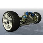 |
| Autodesk Inventor Studio, new in Inventor 10, lets users create photorealistic renderings and animations directly within the design environment. |
Autodesk has obviously been listening to its customers, because most of the enhancements and new capabilities in this release are in direct response to wish-list items and user requests. Improvements to weldments; the new bill of materials features; IGES and STEP import capabilities; improvements to the sketch, part, assembly, and drawing environment; and new rendering and animation capabilities have all been incorporated in response to direct customer feedback. Enhanced Weldments
Many of the enhancements in Inventor 10 improve the program’s machine design capabilities. For example, Inventor has long had excellent tools for creating weldments. Inventor 10 improves upon these capabilities with the addition of 3D gap and groove welding. Users can now classify and model fillet, gap, and groove weld beads as 3D solids. Once welds are simulated in the 3D model, Inventor can automatically create the appropriate weld symbols in 2D documentation.
Weldment analysis and reporting capabilities have also been enhanced so that users can determine weld rod usage, fabrication time, and bead weights. A pane on the Properties dialog box shows values for total mass, area, and volume of cosmetic weld beads in the assembly and Inventor can report all weld information for each document including ID, type, length, mass, area, and volume.
Assembly-Centric Bill of MaterialsInventor 10 also features what Autodesk is calling “assembly centric bill of materials.” For product designers, the bill of materials (BOM) is usually the single source for assembly parts lists and component quantity data. Inventor 10 includes a new BOM Editor that enables users to make adjustments to the BOM structure, define the status of components within the BOM, and change component properties, all using a table-driven interface.
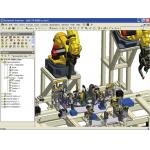 |
| Autodesk Inventor 10 provides new tools and capabilities in direct response to user requests, including weldment enhancements, new BOM capabilities, and patterns of assembly features. |
;)
The BOM Structure property lets you define the status of each component, and provides five basic options: Normal, Phantom, Reference, Purchased, and Inseparable. Normal is the default BOM Structure for most components. They are numbered and included in quantity calculations and their placement in the BOM is determined by their parent assembly. Phantom components are used to simplify the design process. They exist in the design but are ignored by the BOM. Examples of phantom components are sets of hardware where the components are purchased and assembled separately, but are commonly used together (such as screws, nuts, and washers).
Reference components are used for construction geometry or to add context to a design. They are excluded from quantity, mass, or volume calculations and also have special treatment in drawing views. Purchased components are items such as cylinders, pistons, shock absorbers, and hinges and appear as a single BOM line item. Inseparable components are assemblies that would be physically damaged if components were to be disassembled, such as those that are welded or riveted. Inseparable components are generally fabricated rather than purchased.
The BOM also supports virtual components that require no modeling, but still have properties such as quantity, part number, and so on. Examples include bulk items such as gas, air, oil, and grease.
Functional DesignFunctional Design is Autodesk’s term to describe a new approach aimed at helping engineers move from simply creating geometry to capturing and using knowledge about how products function. The new tools—the Design Accelerator, the Feature Generator, and 3D Grips—enable users to create mechanically correct components by entering mechanical attributes.
The Design Accelerator consists of three utilities: Component Generators, Mechanical Calculators, and the Engineer’s Handbook. Component Generators allow you to quickly create commonly used machine components based on functional requirements and specifications. For example, you can create gear assemblies by specifying the type of gearing and geometric parameters. Inventor 10 includes component generators for mechanical connections, shafts and hubs, O-rings, belt and chain drives, power screws, and springs.
Interactive Mechanical Calculators let you calculate fits, tolerances, torque, pressures, and dynamic or static loads. Inventor 10 provides tools to calculate the strength of welded and soldered connections, the strength of clamping joints, the loads on radial plain bearings, the torque and other forces on various types of brakes, the loads on flat plates, and the fit and tolerance of various parts and chains of dimensions.
The Engineer’s Handbook provides an online reference that includes engineering theory, formulas, and algorithms used in machine design. It’s a design reference library accessible directly inside Inventor.
Within the part environment, the Feature Generator provides a new way to edit extrude, revolve, and sweep without having to deal with features, parameters, and constraints, while 3D Grips provides a fast and flexible way to edit parametric parts by dragging these new grip arrows.
Finding Parts and Importing ContentThe new Content Center marks the evolution of Inventor’s Standard Parts Library. It’s a customizable parts library that includes tools for accessing and publishing user-defined content (parts and iParts), an intuitive editor, an update notification utility, and a powerful search tool. All tube and pipe content from Inventor Professional is also included, and users can modify standard content, such as including company-specific part names and numbers. It’s not glamorous, but Content Center should help users work faster.
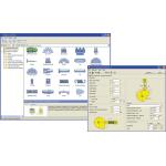 |
| Component Generators, part of Inventor’s new Design Accelerator, enable users to quickly create commonly used machine components, such as cams and gear assemblies, based on functional requirements and specifications. |
Another significant enhancement in Inventor 10 is a new set of tools for importing IGES and STEP files, including tools for inspecting, editing, and correcting imported data. If the original IGES or STEP file is subsequently updated outside of Inventor, users can quickly re-import and redefine the geometry. Associative part relationships and drawings are then updated as needed. Rendering, Animation,and Other pluses
Many customers have asked for the ability to make photorealistic renderings of their models. Autodesk’s response is a new tool called Autodesk Inventor Studio, which provides built-in, state-of-the-art rendering and animation directly in the design environment. Inventor Studio automatically recognizes materials assigned to parts and assemblies. It also includes a range of styles offering lighting setup, surface texture and materials, backgrounds, and cameras to customize the image as desired. For those who want to simulate assembly motion, Inventor Studio includes a suite of key frame animation tools. Designers can utilize their design constraints and parameters or create new motion paths with the animation tool set.
Autodesk rounds out this release with a host of other improvements and new features. For example, when sketching, dimensions based on equations now appear with an ƒ: symbol and users can now create constraint-based 3D sketches with precise coordinates. New modeling capabilities include the ability to create rectangular, circular, and mirrored patterns of assembly features. In the drawing environment, a new utility allows the batch transfer of title blocks, borders, and sketched symbols based on name, group, folder, or project.
Inventor 10 also includes a new Task Scheduler that lets users schedule operations such as printing, importing files, and publishing DWF files.
Autodesk Vault, the data management tool that has been included with all versions since Inventor 7, now includes the ability to copy an entire design, including all related files, to use as the basis for a new design. Vault 4 also now automatically creates DWF files for each file checked into Autodesk Vault.
While Inventor Professional 10 includes all of the enhancements in Inventor, specific changes to its specialized capabilities are more incremental, such as the ability to use frictionless supports when running stress calculations and to derive tube and pipe routes from 3D sketches. Both Inventor and Inventor Professional include AutoCAD Mechanical 2006 (Autodesk Mechanical Desktop 2006), which encompasses all of AutoCAD plus the mechanical-specific enhancements, including the ability to produce associative drawings of Inventor parts and assemblies.
For the first time, the Inventor software comes on a DVD rather than a CD. Those lacking a DVD drive can request a copy of the software on CDs. In addition to the aforementioned software, Autodesk also includes its DWF Viewer for viewing DWF files; Inventor View for enabling non-Inventor users to open and print Inventor part (.ipt), assembly (.iam), and drawing (.idw) files; and the Autodesk DWG Viewer for viewing and plotting AutoCAD DWG files.
The sum of all its many parts makes Autodesk Inventor 10 one of the most significant releases in its nearly six-year history. With it, Autodesk delivers plenty of enhancements aimed squarely at the needs of its growing numbers of users.
David Cohn is a computer consultant and technical writer based in Bellingham, WA. He’s a Contributing Editor to Desktop Engineering, the Editor-in-Chief of Engineering Automation Report and CADCAMNet published by Cyon Research, and the author of more than a dozen books. You can contact David through his website or click here to send him an e-mail about this article.
Inventor 10—At a Glance
Autodesk, Inc.
San Rafael, CA
Inventor Series 10
Price: $5,195; $1,495 upgrade from
Inventor 9; $1,095 annual subscription
Inventor Professional 10
Price: $7,950; $2,795 upgrade from
Inventor Series 7 or newer (upgrades
from earlier versions of Inventor
Professional available through
subscription only); $1,495 annual
subscription
System Requirements
CPU: Intel Pentium 4, Intel Xeon,
or AMD Athlon processor, 2GHz or
higher (3GHz recommended for
assemblies of more than 1,000 parts)
Operating System: Windows XP
Professional (SP1 and SP2) or
Windows 2000 (SP4)
Memory: 1GB RAM (3GB or more
recommended for large assemblies)
Disk space: 3GB free disk space
Video: 128MB or more OpenGL
capable workstation class
graphics card
Other: DVD drive (software available
on CD upon request); Microsoft
Internet Explorer 6 SP1 or later;
Microsoft Excel 2000 or later for
iParts, iFeatures, thread
customization, and spreadsheet
driven designs; NetMeeting 3.01 or
later for Web collaboration
Subscribe to our FREE magazine, FREE email newsletters or both!
Latest News
About the Author
David Cohn is a consultant and technical writer based in Bellingham, WA, and has been benchmarking PCs since 1984. He is a Contributing Editor to Digital Engineering, the former senior content manager at 4D Technologies, and the author of more than a dozen books. Email at [email protected] or visit his website at www.dscohn.com.
Follow DE

