LabVIEW Enables System Simulation
Part 1: Improving the development process using NI simulation tools in combination with MCAD tools and others, such as Simulink.


Latest News
March 3, 2008
By Chris Washington
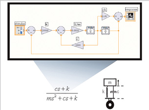 Figure 1: As the tools and technologies for simulation have evolved, the use of graphical block diagrams has become a popular way to create models. This is a representation of an ordinarydifferential equation (ODE) model of a system in textual and block diagram forms. |
This is the first in a series of articles examining how simulation technology developments are impacting the development process.
Engineers increasingly use simulation to meet the growing challenges of system development. Depending on the application, the simulation can be as simple as an additional software routine developed during the design process or it can be the primary medium for creating the design. It could take the form of a simple Boolean-state machine or it could require a multitude of mathematical equations to represent the behavior of a real-world entity.
The benefits of simulation have been well documented. It is used across virtually every engineering discipline to improve the development process and design quality, identify design errors earlier, cut down on physical prototypes, and reduce time to market.
There are, however, many types of simulation and corresponding technologies used to implement them today. Circuit designers simulate the performance of circuits and optimize them in a virtual environment to cut both physical prototypes and the lengthy processes required to achieve the correct design. Biomedical engineers can experiment with medical device implementation with no danger to a living test subject. Process engineers can evaluate the effects of process changes without impacting the actual production of their products. Mechanical engineers can virtually test material or geometric changes to a component, providing greater freedom to evaluate without incurring prototype costs. Controls engineers can begin developing a machine’s control system while constructing it and identify possible catastrophic errors such as collisions in a virtual environment before they do any real damage.
In addition to providing an overview of these possibilities, we examine several real-world applications for which engineers are combining simulation tools with other development tools to improve the development process.
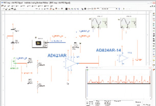 Figure 2: Schematic representations are useful for implementing circuit models because they naturallyconvey the physical relationship of the system components that defines the behavior of the system. |
Simulation and Modeling
For our purposes, the process of simulation typically involves the use of a model of an entity that is solved to imitate the entity’s real-world behavior.
Depending on the application and entity being simulated, a model can be constructed using a variety of techniques. Discrete control systems and digital logic designs are often modeled using Boolean expressions such as AND, OR, XOR, and so on. Algebraic and differential equations are commonly used to represent system dynamics (kinematics), analog circuits, or the physical properties of a system such as heat transfer and strain. For reactive systems, state charts or finite state machines are typically the most intuitive method for describing their responses. Behavioral modeling methods can also be used to represent enterprise systems such as information management or user experience through application user interface models. In real-world applications, these and other modeling techniques are usually combined to provide the ideal representation of the characteristics and behaviors of the entity being simulated.
Just as a model can take many forms depending on the application and entity that is to be simulated, the model itself can be realized using a variety of representations. The textual representation of mathematical equations and programming logic is the original method engineers used to implement their models. As the tools and technologies for simulation have evolved, the use of graphical block diagrams has become a popular method for creating models. Figure 1 illustrates the representation of an ordinary differential equation (ODE) model of a system in textual and block diagram forms.
Schematic representations (see Figure 2, above) are a popular choice for implementing circuit models because they naturally convey the physical relationship of the system components that defines the behavior of the system. While this is a popular method, textual methods such as net lists and hardware-descriptive languages are often more practical for large-scale applications. For mechanical systems, mesh or geometric models are most common because of the importance of the physical linkages between components and the visualization of properties across a gradient of the entity.
Figure 3 shows a model of a prespectrometer in geometric form that an engineer can use to visualize the temperature gradient across the simulated entity.
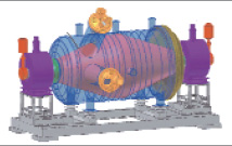 Figure 3: This geometric model enables an engineer to visualize the temperature gradientacross a simulated prespectrometer. |
Simulation in the Development Process
Simulation has become essential throughout the development process. As computing technologies continue to increase and commercial tools evolve to take advantage of these technologies, the ways in which simulation technologies can improve the development process continue to expand.
One example of this evolution is virtual machine prototyping whereby machine builders are embedding more functionality in the controls of the machine as opposed to the mechanical components. To achieve efficient machine design, engineers need to simulate the integrated mechanical and control design in software before moving to the prototype stage. This helps them make tradeoffs in the early stages of design without the need to create prototypes after every design iteration. It also helps them visualize the electromechanical system in action to validate their control algorithm logic without risking damage to a physical system.
The ability to link mechanical design software such as SolidWorks with control system development software like LabVIEW from National Instruments helps engineers fine-tune their control algorithms against high-fidelity simulation.
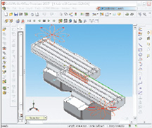 The ability to connect mechanical design software with control system developmentsoftware helps engineers create efficiently. |
Another example is graphical system design of advanced control systems. Graphical system design is a revolutionary approach to solving design challenges that blends intuitive graphical programming and flexible commercial off-the-shelf (COTS) hardware to help engineers and scientists more efficiently design, prototype, and deploy embedded systems. A senior design team at Rensselaer Polytechnic Institute (RPI) set out to develop an interdisciplinary mechatronics system by designing and prototyping a two-wheeled robotic locomotion platform inspired by (and with the permission of) the Segway Corporation, maker of the Segway Human Transporter. The RPI Two-Wheeled Balancing Transport Platform uses parallel-wheel locomotion to provide precise maneuverability while maintaining system stability.
The team tackled the complexity involved in modeling and analyzing the dynamics of the mechanical system by creating a sensor fusion algorithm to increase system bandwidth, developing a robust control strategy, and implemented the design in just four months.
The final example is hardware-in-the-loop (HIL) simulation for improved validation. As control systems increase in complexity, so do their testing requirements. HIL simulation is a test technique that enables more flexible and lower-cost testing of control units by using a model to simulate the system to be controlled by the unit under test. MicroNova developed a flexible HIL test system for engine control units that incorporates its own engine dynamics models created using the Simulink environment developed by The MathWorks, and sensor and actuator models developed using the LabVIEW FPGA Module. All of these models were combined in the LabVIEW Real-Time environment to produce a real-time HIL simulation test system.
The next article in this series will look more deeply into how varied simulation tools can be combined to create efficient development processes.
More Info:
Simulink
The MathWorks, Inc.
Natick, MA
mathworks.com
MicroNova Software and Systems
Vierkirchen,Germany
micronova.de
LabVIEW
National Instruments
Austin, TX
ni.com
Rensselaer Polytechnic Institute (RPI)
Troy, NY
rpi.edu
SolidWorks
Concord,MA
solidworks.com
For more information on virtual machine prototyping technology, please visit http://zone.ni.com/devzone/cda/tut/p/id/6025.
For more information on the technologies used in the RPI project, please visit ni.com/info and enter rpitransportplatform.
For more information on HIL, visit ni.com/info and enter hilsimulation.
Chris Washington is a product manager for the LabVIEW Embedded Software platform developed by National Instruments. Send e-mail about this article to [email protected].
Subscribe to our FREE magazine, FREE email newsletters or both!
Latest News
About the Author
DE’s editors contribute news and new product announcements to Digital Engineering.
Press releases may be sent to them via [email protected].


