

Latest News
August 1, 2008
By Javier Gutierrez
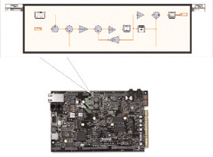 Figure 1: Executing simulation models in hardware. |
Design engineers often face the challenging task of implementing an algorithm created during the design phase of a project into a real-world system. They use one set of tools to model and simulate design performance and behavior, and they use another set of tools to transition the software model into a prototype once they meet design specifications. Oftentimes, a different team of engineers tackles this by translating the previous work into a description that can be used on an embedded target, often using a different platform than that used for final deployment, increasing the amount of work. The deployment process is long, tedious, and prone to mistakes because the latter set of engineers often cannot leverage the efforts made during the design phase. A design-and-simulation tool with hardware integration capabilities could greatly narrow this gap between design and deployment.
How Good Is a Good Model?
Before considering the real-world implementation of simulation models, designers have to ask themselves several questions: What is my final goal? Does my software algorithm need to show all the dynamics of the system or only the most significant? Does the model represent the behavior of a plant, and do I plan to use it on a hardware-in-the-loop (HIL) test system or only to design a control algorithm? How much error behavior can I afford between the predicted response for a given model and the real response from the real system?
With answers to these questions, designers can wisely choose how much time to spend building and refining a model and how much time to spend actually creating the code that is going to be deployed. Simulation models used on HIL testers like those that test the dynamics of a car to help design a cruise-control electronic control unit (ECU) must match the behavior of the real system as closely as possible. The development of such highly detailed models can take several years, as new characteristics are added to the model over time. On the opposite side of the spectrum, if the purpose of the model is simply to capture the essential behavior of the plant needed to develop a control algorithm, then much of the design effort should go toward controller efficiency rather than capturing elements that do not affect the design.
If the physical system is available, engineers can use it to find the mathematical model based on system identification techniques. System identification algorithms, which are fed with the input and response signals to the plant, use curve-fitting and optimization techniques to find the mathematical model that better matches the signals. Another use for real signals from the plant is to fine-tune the simulation model if it has been derived by other means. One way is to feed both the real system and the simulated system with the same set of stimulus signals and compare the real and simulated results. A third option, if the physical plant is available, is to mix system identification with plant modeling using ”gray-box system identification” to estimate unknown parameters in a partially known model.
|
It is well known that one of the benefits of simulation in the design process is that it allows you to work on a problem even without having the physical system present. But when there is a physical system to which you can add inputs and outputs, you can use the resulting information to fine-tune the model.
Considerations BeforeDeploying to Hardware
When working in a simulation environment, many of the signals and systems you use have an “ideal” representation. Consider the following before deploying your model to hardware to reduce unexpected responses:
Noise: In a real-world system, noise is always present in the signals used. It can come from a variety of sources such as power supplies and environmental conditions. When working with low-level signals in your simulation, the presence of noise can greatly affect your results.
Sampling rate: Computer-based systems are discrete in nature and can gather information from a system only at finite moments in time. The state between one sampling point and the next is assumed to be constant. Modeling does not have this limitation because typical modeling environments can change time steps dynamically to better capture the system transients.
Loop rates: Loop rates are the speed at which you are executing the control loop, and the speed might not coincide with sampling rates. Typically, simulations assume the controller can keep up with the loop rates, although this might not actually be true because it depends on the hardware target you are using (both processing power and operating system (OS).
Resolution: When using values to describe magnitudes on a system, you should typically use a double-precision floating point representation. This data type is capable of reproducing real-world values more accurately than the integer-based or fixed-point-based data types found in microprocessors and digital signal processors (DSPs). This loss in information might lead to instabilities or unexpected behavior.
Determinism: Most control systems are driven by a fixed time step. For the real world to match simulation, the hardware that drives the model implementation must be capable of doing all the processing in the allotted amount of time. In the case of control systems, they include not only the control algorithm and the I/O calls, but also some extra tasks such as data logging, safety control, and so on. This depends on the hardware processor as well as the type of OS that the control system is running.
Sensor delays: When working with simulations, information from the sensors and actuators is — most of the time — assumed to be instantaneous. Both sensors and actuators have their own dynamics and delays that might affect the overall simulation.
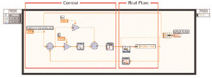 Figure 3: LabVIEW Simulation Loop with real brushed DC motor. |
Closing the gap
All the above considerations can help you develop implementation models with predicted responses that better match the physical systems they represent. But the main challenge remains to be addressed: How do you bring the simulation models from design into a hardware system?
At this point, you can choose from several design paths. One of the most common is to document the desired system behavior and hand it over to an embedded-design team. This path is time consuming, and it requires a multidisciplinary team with knowledge of different tools. Some simulation packages have the capability to generate code that represents the model being developed. This is a great improvement over the previous path, but the team of developers is still needed to add the required I/O.
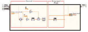
Still, there is a third option where the modeling environment can handle all the necessary code for both the model and the I/O. One example of this option is National Instruments LabVIEW software and the LabVIEW Control Design and Simulation Module. You can use the simulation capabilities of the module to design a model and overcome the limitations mentioned above. Because the module is built on the LabVIEW programming environment, it can leverage all LabVIEW functions such as the I/O calls for analog and digital signals, CAN messages, and serial communication. Figure 2 shows a screenshot of a LabVIEW VI that represents the simulation of a brushed DC motor controlled by a discrete PID controller with saturation.
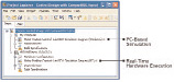 Figure 4: Project-based configuration. |
By adding the necessary I/O hardware calls, you can replace the simulated plant (brushless DC motor in this example) with the actual code necessary to interface with the real-world system without the need for compiling or handing the code to another team. Figure 3 shows an example of how you implement this.
Once you have set up the I/O, the next step is to deploy the code to a real-time hardware target. Again, you can take advantage of LabVIEW technologies to define on which previously configured machine the code has to run.
As design engineers work to increase the quality and throughput of their designs while reducing time to market, new ways to optimize the design flow have been developed. Some programming languages, like LabVIEW, add simulation capabilities to hardware connectivity and allow for easier and effortless transitions, from design and simulation to real-world hardware deployments.
More Info:
National Instruments
Austin, TX
ni.com
Javier Gutierrez is a control systems engineer at National Instruments and has worked for NI for more than seven years. He manages the Control Design and Simulation product line. Send e-mail about this article to [email protected].
Subscribe to our FREE magazine, FREE email newsletters or both!
Latest News
About the Author
DE’s editors contribute news and new product announcements to Digital Engineering.
Press releases may be sent to them via [email protected].


