

Latest News
July 27, 2009
By Kenneth Wong
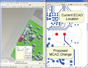 The ECAD-MCAD collaboration extension, the outcome of a partnership between Mentor Graphics and PTC, facilitates concurrent electromechanical design via an interface that shows ECAD and MCAD files side by side, allowing engineers in to both check interferences and propose changes. |
Electrical engineering revolves around connectivity, wiring, and voltages. By contrast, mechanical and industrial design focuses on geometric shapes, surfaces, masses, and aesthetics. Over the years, driven by the fundamentally different domains they serve, electrical CAD (ECAD) and mechanical CAD (MCAD) packages evolved as two distinct software species.
But the recent push to embed electronics in everyday products—from portable media players to voice-responsive automobiles—is forcing the two disciplines to come together. Whatever your next generation product is, its electronics cannot be an afterthought. They must be part of the design process, from concept to manufacture.
We’ve decided to examine some products that let ECAD and MCAD users communicate with each other via a common language (so to speak). To solve integration issues, developers have devised interfaces that they feel will serve both disciplines best; they make bets on the data formats or schemas that they believe will become the lingua franca of electro-mechanical exchange.
Mentor Graphics and PTC
The origin of Mentor Graphics and PTC’s ECAD-MCAD collaboration can be traced back to 2005, when Mentor Graphics joined the ProSTEP iViP Association’s ECAD Implementor Forum (ECAD-IF). Project participants included, among others, Daimler AG, Volkswagen AG, Delphi Deutschland GmbH, PTC, and Siemens PLM Software.
In September 2008, using the newly defined STEP-based ECAD-MCAD data exchange protocols, PTC and Mentor Graphics released what they described as “the first ECAD-MCAD collaboration capacity.” A view of each domain—the printed circuit board (PCB) layout and the MCAD model—are displayed side by side. When a mechanical engineer adjusts one component on the MCAD model, it will automatically show the effect on the ECAD layout, and vice versa.
CircuitWorks for SolidWorks
SolidWorks got its own ECAD extension by snatching up CircuitWorks, one of its Gold Partner developers. Whereas PTC’s extension allows users to see proposed changes and accepted states side by side, CircuitWorks lets users incorporate a PCB design file as a subassembly within a SolidWorks assembly via IDF (intermediate data-exchange format) and PADS file formats, both commonly used to describe PCB designs. Conversely, you can also export a SolidWorks assembly in the IDF format for PCB design programs.
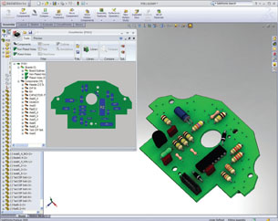 CircuitWorks lets SolidWorks users incorporate PCB components as part of the solid assembly. |
With CircuitWorks, users can incorporate the embedded PCB components as part of the finite element analysis (FEA) process via COSMOSWorks (recently renamed SolidWorks Simulation), ANSYS, or other similar packages. CircuitWorks is compatible with leading ECAD software, including Cadence, Mentor Graphics, and Altium.
Siemens’ Connection Agents
Siemens PLM Software relies on third-party developers like Desktop EDA and TLD to supply the ECAD integration function to Solid Edge. Desktop EDA began life as an enhancement developer to EDA (electronic design automation) software maker Altium’s ECAD platform. Its premier product was an AutoCAD translator for Altium Designer, but it has since developed bidirectional ECAD bridges for Autodesk Inventor, Solid Edge, and SolidWorks. Like CircuitWorks, Desktop EDA modules let you import PCB design as assembly components, then export the edited PCB design back into the original ECAD system. Desktop EDA’s products use IDF format to shuttle files back and forth.
Similarly, Washington-based TLD’s PCBto3D software uses IDF and PADS ASCII formats to bridge ECAD and Solid Edge. According to TLD, if you use the IDF format, you can make changes to the board design in Solid Edge using standard Solid Edge editing commands; and you can use PCB-specific commands that are added to Solid Edge when PCBto3D is installed.
Dassault Systèmes’ PCB Links
Last June, the partnership between Dassault and PCB software supplier Zuken gave birth to the Board Interchanger, an ECAD-integration module embedded in Dassault Systemes’ CATIA. Based on CAA V5 (the programming platform for CATIA), Board Interchanger is developed to let MCAD engineers verify 3D floor-planning of electronic components and check collisions with housing components. The module serves as CATIA’s link to PCB files created in Zuken’s CR-5000 Board Designer software.
CATIA also offers a Circuit Board Design module that allows mechanical engineers to pass along a PCB layout in IDF format to electronics designers. According to the company, the software is designed for creation and management of electronic component catalogs and intelligent placement of connectors in its mechanical environment.
Altium Pushes for Native CAD Support
In a video clip at Altium’s site (“Episode I: Next Generation Electronics Design”), an announcer explains the company’s philosophy on MCAD integration: “For years, we did what a traditional EDA company would do. We provided the same solution as everyone else—generate the 3D file so you could throw them over the wall to the MCAD guys. The problem was, we kind of knew this wasn’t working too well.”
A more effective approach, according to Altium, is a unified solution with 3D PCB layout linked dynamically to MCAD programs. Rob Irwin, the company’s product marketing manager, says, “We now provide natively a full ‘live’ 3D design environment for PCBs that can link directly to external STEP models. So with Altium Designer (and no add-ons), it is possible to bring the 3D model of the casing into the PCB design environment, perform full fit and clearance tests, make any adjustments to the PCB interactively in the 3D space, and export the PCB as a STEP file for import into any mechanical design package.”
Irwin pointed out, “For the majority of people, exporting all ECAD data to an MCAD system is pretty pointless as the electrical elements typically don’t affect mechanical analysis. Hence, we provide the means to export only the truly mechanical elements of a PCB design back to the MCAD system … With Altium Designer, the PCB designer has direct access to the 3D case data and can interactively adjust the position of components….”
 Altium Designer offers dynamic links to external STEP models. The result is, according to Altium, a “bidirectional interactivity between mechanical and electrical designers.” |
Harnessing MCAD
For incorporating electrical setups much more complex than those found in consumer electronics, Synopsys offers Saber Harness, an electrical wire-harness layout and design system meant for automotive manufacturers. In the product data sheet, Synopsys describes it as a software that “allows designers to create schematic drawings and connectivity diagrams, export component and wire data, import geometry information from MCAD tools, simulate electrical functions, create bundles with connector positions and generate data for manufacturing—all within one easy-to-use tool.”
Synopsys’ Saber Harness can be deployed with Dassault’s CATIA, Siemens’ NX, and PTC’s Pro/ENGINEER. It comes with a proprietary wire editor for creating connectivity schematics from scratch. The software’s check-in/check-out mechanism ensures that concurrent edits taking place over multiple subschematics don’t accidentally overwrite one another. Afterwards, users can export the entire electrical wiring scheme into a 3D CAD system to further refine the placement and fitting.
Electrical Interconnections
In the same month Mentor Graphics joined the ECAD-IF, the company also inked a joint-cooperation agreement with UGS (now Siemens PLM Software) to tie Mentor’s Capital Harness Systems (CHS), a suite of products for electrical interconnect systems, to NX CAD software.
A year later, in May 2006, Mentor Graphics made good on its promise. It delivered integration functions that let CHS publish harness data to both Teamcenter and NX so users can exchange wiring, topology, and mechanical harness descriptions. Now Solid Edge offers a wire harness application that can read Netlist schematic files from various ECAD packages for automatic harness design. In essence, you can use the electrical connectivity defined in the electrical schematic for creating physical wires and cables in the 3D CAD package. Once the connection data is imported into Solid Edge, the wires or cables are automatically created between components. Solid Edge tools will also determine the harnesses’ manufacturability and obtain wire cut lengths.
Building Bridges
The bidirectional interoperability found in these ECAD-MCAD integration products ranges from the ability to pass electrical and mechanical data back and forth as STEP and IDF files to dynamic links that automatically update when a design is altered on either end. If your workflow is sequential, or if you work in silos (in other words, one department finishes off something, then passes it along to another), the ability to exchange ECAD and MCAD geometry accurately might be more crucial than dynamic updates. On the other hand, if you develop the electronics and mechanics in parallel, you may favor products that offer dynamic links and automatic updates to keep versions in sync.
A software package developed to define the PCB architecture and wire layouts is seldom suitable for designing, say, consumer products with complex profiles and extruded faces. By the same token, the modeling engine of a mechanical design system would have been overkill for the relatively simple geometry required to construct a PCB layout. For these reasons, developing a single product to address both electrical and mechanical designs is, at least for the foreseeable future, not a feasible proposition. So the use of data bridges—nested ECAD support in MCAD applications, STEP translator for PCB design, and others—remains the preferred solution.
More Info:
Related article: CircuitWorks 9
Altium Ltd.
Sydney, Australia
Dassault Systèmes
Paris, France
Desktop EDA
Bundoora, Australia
Mentor Graphics Corp.
Wilsonville, OR
ProSTEP iViP
Darmstadt, Germany
PTC
Needham, MA
Siemens PLM Software
Plano, TX
SolidWorks
Concord, MA
Synopsys
Mountain View, CA
TLD
Bellevue, WA
Zuken, Inc.
Yokohama, Japan
Kenneth Wong writes about technology, its innovative use, and its implications. He has written for Computer Graphics World, Cadalyst, Game Developer, and Manufacturing Business Technology. You can reach him at [email protected], follow him on Twitter at KennethWongCAD, or send e-mail about this article to [email protected].
Subscribe to our FREE magazine, FREE email newsletters or both!
Latest News
About the Author
Kenneth Wong is Digital Engineering’s resident blogger and senior editor. Email him at [email protected] or share your thoughts on this article at digitaleng.news/facebook.
Follow DE

