

December 10, 2007
By Pamela J. Waterman
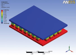
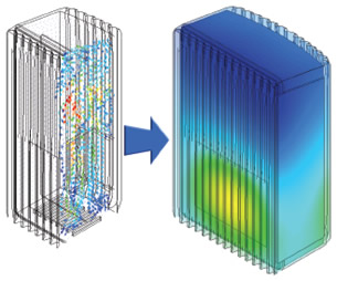 GE Healthcare-Monitoring Solutions used ALGOR’s multiphysics capabilities to analyze this patientmonitoring unit. A steady, coupled fluid-flow and heat-transfer analysis determined the internal airflowcharacteristics (left) and the distribution of the external surface temperatures (right). |
If DE were a daily newspaper, the following headline would accompany this story: Multiphysics Storms Analysis Industry.
Alliances, mergers, ever-advancing computational algorithm breakthroughs, and a surge in affordable computing have combined to put multiphysics capabilities in the hands of thousands of design engineers, and they are paying attention. In a recent company newsletter, COMSOL Vice President of Marketing Bernt Nilsson made this observation: “Back in August 2004, a search on Google pulled up 13,000 hits for the term ‘multiphysics.’ Now it’s at 421,000.” Solutions are matching needs like never before.
To aid readers in discovering how their projects could benefit from simultaneously incorporating two or more types of physics during analysis, DE explores several state-of-the-art applications.
Taking the Heat
Dealing with coupled, interdependent phenomena is a crucial aspect of successful designs for Marlow Industries in Dallas, Texas. The company specializes in manufacturing thermoelectric (TE) coolers for use in such systems as pump lasers, bio-analytical instrumentation, and high-performance liquid chromatography. Many of its designs apply the Peltier effect, whereby the flow of an electrical current through dissimilar conductors results in a desired temperature gradient across the system.
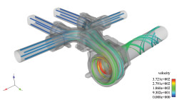 Gas flow streamlines showing turbulent flow through an automotive exhaust manifold section. Image generated by EnSight postprocessing software, using data computed with ADINA-CFD analysis software.(Image courtesy ADINA) |
|
Robin McCarty, senior R&D engineer at Marlow, says that one case where TE devices are particularly useful is for cooling small laser diodes. She notes, “Understanding the stresses ]within devices a mere quarter-inch square] is critical for avoiding mechanical failure. Because our devices are manufactured using many different components including TE material, ceramics, metallization, and solder, and experience many different temperature environments, they can have stresses built into them during the manufacturing process and typical operation.”
To begin a project, customers supply geometry and thermal specifications, then Marlow applies both thermal and electrical boundary conditions to determine a value for the desired “cool-side” temperature. McCarty explains, “We are using ANSYS software to first model the thermoelectric effect predicting the thermal performance of the device. We have to convert thermal finite elements (FE) into thermoelectric FEs, then apply a voltage to the device boundary.” The company designs an appropriate structure in which current flows generally in an up-down pattern through small TE “bricks” to electrical connectors sandwiched between two metallized ceramic plates. The Peltier effect lowers the temperature of the attached, target device (e.g., a laser diode).
McCarty then uses this temperature condition to run a Static Structural model on the TE cooler to identify the regions with the highest stresses. In the past, the corners of the devices have displayed problems; the ANSYS analysis correlated to what Marlow noticed was happening in those areas. “Based on this insight,” says McCarty, “we redesigned both the geometry and the materials of the devices to lower the stresses in the corners. For example, we found that making a cut in the center of the ceramic was helpful. Before using ANSYS, we never had the capability to get both the thermoelectrical and mechanical solutions in one environment.”
Managing Exhaust Flow
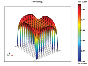 COMSOL Multiphysics’ plot of temperature across a detector array. Temperature differences are smalland can lead to noise if not compensated for in their position in the array. (Image courtesy COMSOL) |
Combining the results of fluid-flow, thermal, and structural analyses for a new automotive exhaust-manifold design proved tricky for a Tier 1 supplier until it approached the problem with ADINA-CFD and ADINA-Structures software. With this project, the company faced three main challenges. First, the software had to be capable of analyzing and predicting three different, interdependent physics: turbulent fluid (gas) flow through the manifold; structural FE analysis of the part itself with all its components, allowing for contact, bolt pre-loading, and both with and without creep (time-dependent deformation due to high temperature stress); and coupled thermal analysis of both the fluid and solid parts.
Second, the designers wanted to make use of FE meshes that had already been independently done on several components of the exhaust assembly. And third, the sheer size of the model that was set up made the overall analysis a challenge: 10 million fluid equations with velocity, pressure, and turbulence variables, 5 million temperature equations, and 1.8 million structural equations containing displacements and contact forces.
For many solvers calculating fluid-structural interaction, this problem could not be fully defined, would not converge, or took an unacceptably long time to solve. However, by using the two ADINA software packages working within the same environment, the customer was able to tackle each of these issues successfully. The mesh-gluing feature within ADINA-Structures took care of the non-matched meshes between structural parts, and the sliding-mesh feature of ADINA-CFD took care of the same problem when defining the fluid.
| 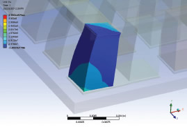 Close-up of thermoelectric (TE) corner “brick”in the TE cooler device, showing resulting principal stress identified with an ANSYS analysis. Subsequent mechanical redesign of the upper ceramic plate greatly relieved this stressconcentration. (Image courtesy Marlow Industries) |
The memory used for the solid model was 7.8GB; for the fluid model it was 6.3 GB. For an analysis without creep effects, the overall solution time was 11 hours and eight minutes.
New Meaning for “Above The Noise”
Telescopes serve as eyes into both space and time, and scientists keep pushing the limits on both fronts. The European Space Agency, in conjunction with various commercial, governmental, and academic groups, is working on a mission to study the evolution of the universe by “viewing” faint x-ray emissions generated just a billion years after the Big Bang. Data from a new x-ray telescope will help fill in our understanding of the first massive black holes and galaxies, predecessors of the clustered structures we observe visually, as well as at other wavelengths, today.
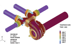
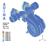 Final stress analysis results on an exhaust manifold, based on multiphysics-coupled analysis with ADINA-Structures and ADINACFD, incorporating fluid-flow effects and temperatureconditions. (Image courtesy ADINA) |
XEUS, the x-ray evolving universe spectrometer, with a scheduled launch date of January 2014, comprises two structures. A 10-meter “lens” and an unattached detector/receiver system will maintain an astounding 50-meter distance, ± 0.25mm, all while orbiting in space. The task of designing the sensitive detector presents a particularly boggling challenge, taken on by physicist Dr. Marcel Bruijn of the Space Research Organization Netherlands.
“The detector’s pixels must measure the energy of x-rays coming from millions of light-years away,” explains Bruijn. “To do so, the detectors must filter this incoming information out of ]unrelated] noise coming from the universe. We can do so in part by maintaining the pixels at a temperature of a few milliKelvin, but good geometric and thermal design is also essential.”
The researchers are hoping to gain a sensitivity factor of more than 200 over that of the current x-ray telescope, XMM-Newton, and have done so for a single pixel design. COMSOL Multiphysics analysis software is helping them model the structures’ behavior to minimize prototype construction.
Each pixel is made from two coupled geometries: a bismuth plate absorber and a superconducting transition edge sensor (TES) that functions as a thermometer. In the absorber, x-rays that hit the plate are translated to heat energy through the movement of electrons and the vibration of crystalline lattices. Any mathematical model of the absorber must consider different relationships in heat capacity and conductivity to accurately calculate the heat flux passed along to the TES.
Multiphysics FAQs A multiphysics analysis combines the effects of two or more physics phenomena into one single analysis. Each physics is represented by one equation system. A multiphysics simulation is represented by a series of intertwined equation systems that all need to be solved simultaneously to get a converged solution. Q: What are some criteria for deciding when you need to incorporate more than one type of physics in an analysis? Q: How does bidirectional coupling come into play? Q: Can different time-scales and mesh-scales be used? FAQs courtesy COMSOL, Inc. |
Heat in the TES affects its electrical conductivity, so changes in the current density correspond to the energy of the original x-ray photon. COMSOL enabled Bruijn to model both geometries separately while setting up the simulation, then solve it simultaneously as a true coupled problem. The researchers also found it convenient that the software readily handles the highly nonlinear equations that define the heat capacity and thermal-electrical conductivity of the materials.
Bruijn’s group is close to producing a 5 x 5 prototype pixel-array, and hopes to eventually build a 32 x 32 pixel unit, continuing to use COMSOL to understand even how the “landing” position of a single photon on the larger array will affect the accuracy of its measured energy value.
Smaller, Cooler,
and Coffee-Resistant, Too
Medical applications demand their own set of exacting specifications for use in a hospital environment. The Monitoring Solutions division of GE Healthcare in Milwaukee, WI, used ALGOR multiphysics capabilities for steady, coupled fluid-flow and heat-transfer analysis to study a concept for a new patient-monitoring unit. The unit houses sensitive electronic equipment used for patient care. Unique environmental thermal loads include high ambient temperatures, confined areas, and close proximity with other heat-generating equipment.
“We were challenged with designing a unit that could dissipate twice the power as the current design while reducing the size by 50 percent,” said Mark Hughes, GE mechanical analysis engineer. “We were further challenged to design a thermal solution that did not require a fan and used minimal venting. Additional requirements included surface temperature limits, two different mounting orientations, surviving fluid ingress, and making the unit easy to clean.”
The multiphysics analysis results allowed Hughes to examine the internal airflow characteristics and external surface temperatures. “Using ALGOR FEA software to simulate concepts before physical prototypes were built helped us to determine if the design concept was feasible. It saved us both time and money and gave us confidence that expensive tooling changes would be minimized.”
More Information
Adina R&D, Inc.
Watertown, MA
adina.com
ALGOR, Inc.
Pittsburgh, PA
algor.com
ANSYS, Inc.
Canonsburg, PA
ansys.com
Computational Engineering International (CEI)
Apex, NC
ensight.com
COMSOL
Burlington, MA
comsol.com
GE Healthcare – Monitoring Solutions
Milwaukee, WI
gehealthcare.com
Marlow Industries
Dallas, TX
marlow.com
Space Research Organization Netherlands (SRON)
Utrecht, The Netherlands
sron.nl
Contributing Editor Pamela J. Waterman is an electrical engineer and freelance technical writer based in Arizona. You can contact her about this article via e-mail sent to DE-Editorsmailto:[email protected].
Subscribe to our FREE magazine, FREE email newsletters or both!
About the Author
Pamela Waterman worked as Digital Engineering’s contributing editor for two decades. Contact her via .(JavaScript must be enabled to view this email address).
Follow DE

