

Latest News
August 1, 2010
By Pamela J. Waterman
As natural as breathing. That phrase takes on new meaning when a medical condition makes ordinary breathing a moment-by-moment struggle.
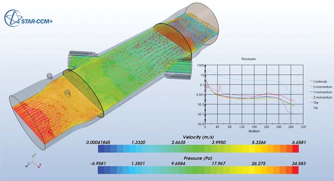 Plane-section pressure profile and velocity vector field for gas flow through a respiratory device component, showing effects of cross-sectional geometry transitions and flow conditioners. Analysis done with CD-adapco’s STAR-CCM+ software. (Image courtesy CareFusion) |
We generally don’t think about our blood circulating until someone mentions heart attack or stroke. But in the medical field, these fundamentally human functions translate into daily design challenges as device manufacturers strive to understand and improve their life-critical products. DE looks at several design projects where computational fluid dynamics (CFD) software sheds light on complex fluid behaviors.
Taking the Burden off Testing
In most projects, early-stage research leads to multiple design concepts, any of which may lead to a great product. But because no company can afford to build them all, CFD can be invaluable in identifying the best possibilities before anything gets built. Dr. Chris Varga has seen that firsthand in his position as senior principal research scientist at CareFusion, a global medical technology company.
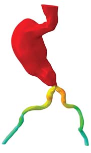 Contour plot obtained with Abaqus/CFD analysis software, showing the variation of pressure inside an abdominal aortic aneurysm sac at a certain instance of the cardiac cycle. (Image courtesy SIMULIA) |
Varga’s division has a long history of designing respiratory care systems and diagnostic products, going back more than 50 years. Since 2006, it’s relied on CD-adapco’s STAR-CCM+ software to quickly analyze gas flows through ventilator components, breathing devices, diagnostics systems and disposable medical devices, visualizing such parameters as pressure, temperature and velocity through certain geometries.
“With traditional build-and-test development, we have limited access through external measurement ports, so we can’t get at the same information that we can with CFD,” he points out. “With STAR-CCM+, we can iterate through tons of concepts and refine them. We have a high confidence level that after being built, they’ll be ready to do what we expect them to do.
“Another aspect of CFD that is a little underappreciated is that it allows us to really push the envelope with aggressive, even wild ideas and test them virtually,” Varga adds. “It lets us take more chances, where we probably wouldn’t have had the support to build them. The cost is just a few hours of computer time.”
His group also uses the STAR-Works package (a version of STAR-CCM+ embedded in Dassault Systèmes’ SolidWorks), allowing the engineers to rapidly evaluate the effects of design changes without requiring deep knowledge of fluid behavior or solid meshing techniques. On a current project, Varga estimates that using CD-adapco’s packages has saved them tens of thousands of dollars in prototyping costs—and weeks to months of building and testing time.
Understanding Flow Anomalies
Nuclear plant reactor experience may not seem immediately relevant to medical device design, but for Enfield Technologies’ Principal Engineer Dan Cook, it served as the key to understanding valuable CFD analysis results. The company produces pneumatic control systems, including precision valves. Most deal with choked-flow applications where the valve regulates high differential pressure (DP) flow (upstream minus downstream) based on simple flow profiles and well-behaved equations.
The valve for one customer’s portable respiratory system, though, needed to operate in a non-linear manner, with a slowly increasing flow profile for 50% of the valve movement and a sharper increase for the second half. The project required a rather large, but precise servo-controlled valve that could regulate air flows up to 200 standard liters per minute (SLPM) while operating with a low DP of about 16 cmH2O (a medical field unit of pressure analogous to mmHg). The company chose a basic “poppet” valve design, with a sealed sliding stem to control the flow-port opening and closing.
Various designs done in Autodesk Inventor were built and tested as part of the complete software-controlled, electromechanical respiratory system, generating preliminary flow-profile data with the valve at different open/closed percentages and under a range of operating conditions. During these physical tests, an odd flow anomaly occurred at approximately half-stroke: When increasing the initial flow, the flow value suddenly dropped by 3%. Reversing the motion did not restore the flow-rate value.
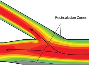 ANSYS CFX analysis of blood flow in branched region of an artery, showing predicted recirculation zones. (Image courtesy University of St. Thomas) |
Cook used Blue Ridge Numerics’ CFdesign software to easily upload the Inventor solid model and recreate the pneumatic system. He set up input pressures, back pressures and upstream restriction coefficients and quickly ran several simulations, using the cut-plane function to see velocity and pressure characteristics at exact points along the flow streamlines. These visualizations clearly showed an area of instability just when the valve was near the 50% open position.
Remembering a theory associated with nuclear reactor physics, Cook speculated he was seeing an unusual bi-stable flow effect that would have been almost impossible to isolate without the CFdesign results and visualization tools. The software allowed him to view the unbalanced flow, messy vortices and crossing streamlines caused by the original internal valve geometry. With this insight, his team was able to change the geometry details and create the desired smooth flow profile.
“The proper application of a powerful tool like CFdesign can mean the difference between winning and losing contract dollars,” he says.
Analyzing Blood as a Transport Fluid
At the University of St. Thomas in St. Paul, MN, analyst John Abraham has been using ANSYS software for more than 15 years while teaching the intricacies of such mechanical engineering topics as heat transfer and fluid flow. As an industry consultant, he recently used ANSYS CFX to simulate pulsating blood flow in an artery that has undergone an orbital atherectomy for plaque removal.
This procedure involves a micro miniature, almost whip-like, diamond-tip catheter-wire that abrades plaque as it traces an offset spiral path through the artery. Centrifugal motion presses the tiny tip outward into contact against the artery wall, hardly blocking any blood flow while it does its “sanding” job. Most of the loosened plaque particulates are smaller than red blood cells and should flush out along with normal blood flow.
The goal of Abraham’s work was to predict whether the moving particulates would travel deep into the capillary structure, possibly leading to clotting, or flow directly through the larger arterial branches. Previously, such understanding could only have been gained through a series of very expensive and complicated experiments performed with custom-made glass models.
To conduct the CFD simulation, Abraham first used MRI images from an actual patient to construct CAD geometry of the arterial system. Because of the excellent CAD file-integration and meshing capabilities of ANSYS CFX, he was able to easily create the relevant fluid-flow region and set up the input parameters. He adds that ANSYS is also able to track particles very well.
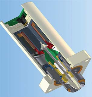 Cutaway CAD diagram of respiratory system valve that displayed an operational anomaly in need of analysis with CFdesign software. (Image courtesy Enfield Technologies) |
CFD analysis predicted that the particles would indeed flow properly along with the red and white blood cells in the plasma, without clogging either capillaries or down-stream sections of the arteries themselves. As a follow-up, Abraham’s group did have the full-scale arterial model built in glass and pumped dye through it at the appropriate pressure. However, many fewer tests were needed to verify the expected behavior, thanks to the CFD results on hand.
Fluid-structure Interactions in the Real World
It’s hard enough modeling and investigating biofluid behavior under textbook conditions, but often the challenge involves simulating a damaged or diseased system. That task falls in the family of problems that SIMULIA is addressing even more than before with new multiphysics capabilities in Abaqus 6.10 Unified Finite Element Analysis software.
While Abaqus still offers co-simulation coupling with other analysis software, including full CFD connectivity with packages from such companies as CD-adapco and ANSYS, the 6.10 version offers internal Abaqus CFD capabilities that go beyond simple coupled Lagrangian methods for fluid-structure interaction analyses. The software uses a hybrid finite element/finite volume approach that takes away typical user concerns about how to integrate the solid model with the CFD analysis set-up. Targeted initially to structural engineers, Abaqus CFD now addresses laminar turbulent fluid flow and thermal behavior. It also addresses interaction with structures, which themselves can behave in a nonlinear manner.
Subham Sett, SIMULIA’s Life Sciences lead engineer for medical devices, recently worked with CFD users in that industry to understand the critical parameters that define various cardiovascular flow situations.
“One application example is that of a simplistic convergent/divergent nozzle to represent a blood-handling, ventricular assist device; that’s pretty straightforward,” Sett says. “Another, more realistic example is that of (simulating) flow through an abdominal aortic aneurism (AAA) through a full cardiac cycle.”
He points out that setting up the boundary conditions for the latter case requires FSI analysis based on non-Newtonian behavior, flexible arteries and similar material densities, all of which present quite a challenge—especially when a stent has been implanted in the damaged area.
“You don’t know what kind of realistic loading conditions to give,” he says. “As a first step, engineers think that if they can get some realistic loads coming from the fluid, and apply it on the structure, ‘Maybe I have a better chance of designing a better product.’”
What Sett likes about SIMULIA’S CFD implementation is that it gives users a chance to remove some of the typical approximations in their analyses, and gain stability in the operation of coupled CFD/FE code. Improved credibility is key to solving such problems as predicting whether a stent, once in place, will experience forces that actually displace it over time.
CFD: A Modern Medical Miracle
Accurately simulating the interactions between intricate medical devices and the wide range of possible fluid behaviors seems a staggering job, but today’s CFD packages are certainly making progress in doing so. Advances in modeling, multiphysics, usability and visualization are helping engineers improve product performance while saving time and money in development.
What’s next? As SIMULIA’s Sett says, “The Holy Grail will be when they can do all of this and account for all the intricacies and behaviors of the human system.”
More Info:
ANSYS
Autodesk
Blue Ridge Numerics
CareFusion
CD-adapco
Dassault Systèmes
Enfield Technologies
SIMULIA
University of St. Thomas
Contributing Editor Pamela J. Waterman, DE’s simulation expert, is an electrical engineer and freelance technical writer based in Arizona. You can send her e-mail to [email protected].
Subscribe to our FREE magazine, FREE email newsletters or both!
Latest News
About the Author
Pamela Waterman worked as Digital Engineering’s contributing editor for two decades. Contact her via .(JavaScript must be enabled to view this email address).
Follow DE

