

January 1, 2013
- work within today s CAD-embedded programs;
- use tools native to a separate analysis package; or
- bring in a specialized third-party tool.
Complexity generally increases with the size of the model, the physics involved, or the number of physics you’re studying. Keeping these factors in mind should help you evaluate options. DE takes a look at a number of these meshing approaches—with their strengths and trade-offs—to put you on an efficient pre-processing path.
From CAD on up
Pointwise has almost three decades of experience in computational fluid dynamics (CFD) pre-processing, so Rick Matus, the company president, has a broad perspective on the topic.
“There is a ladder of increasing control ]and decreasing automation] as you move from CAD-embedded CFD to standalone CFD packages, to adding a separate CFD meshing package like Pointwise,” Matus explains. “Likewise, as you look at the people using these various CFD approaches, you are moving from someone doing basic fluid flow to someone doing more difficult applications, to someone with difficult applications and demand for accuracy.”
Stephen Endersby, SolidWorks senior product manager, sees a similar variation along the spectrum of the tools themselves: “Most CAD packages are good at capturing geometry. If you have an embedded mesher, because you have access to the actual feature history parametrics, you re probably going to capture the geometry very precisely.”
Endersby notes that an external mesher may have a harder task, as it has to do some recognition of the geometry. This task can take more time, but that mesh will probably still be of equal worth.
However, he adds, if you also need to capture stress changes and gradients, you need adaptive meshing capabilities that recognize, perhaps, the need for a finer mesh in the area of a fillet or sharp corner. Today s SolidWorks can do a great deal of that, too, and may be sufficient.
The target audience for doing analysis within CAD programs is the generalist mechanical engineer (as well as an analyst), and that person may or may not have also created the geometry. With this group in mind, Christos Katsis, PTC vice president of R&D simulation software, notes his company s Creo Simulate software tries to automate the numerical controls that the analyst has to use.
“By being an integral part of the CAD environment, having an intimate knowledge of the geometry, we can provide powerful ways to automatically clean up or heal defects,” says Katsis. “Additionally, not only in Creo Parametric but also in Creo Direct, there are tools to simplify ]the model] by suppressing features or modifying geometry.”
If you re using a product data management (PDM) system, you can store iterations of the model.
“Given the direct associativity between the simulation and the CAD model, doing edits for what if studies or sensitivity and optimization studies can be performed without additional work,” Katsis says. “You may only need to partially remesh.”
Have FE/CFD Software, Will Mesh
As soon as you start looking at meshing from the perspective of the finite element analysis (FEA) or CFD analysis software developers, you find many more ways to approach the task. Your choice will depend both on what software you re used to and the level of complexity of your project.
NEi Software now offers NEi in-CAD for SolidWorks (a progression from NEi Fusion), as well as NEi in-CAD for IronCAD, supporting meshing and analysis within a familiar environment. For more analysis-heavy users, the company markets a version of Siemens PLM Femap pre-processing/meshing software optimized for use with NEi Nastran in its various flavors.
Nick Trebilcock, NEi Software product development manager, points out one difference where the latter approach may be preferred, noting, “CAD models are modeled with mathematical accuracy, but may not actually be modeled with real-life accuracy.”
Mitch Muncy, NEi s director of engineering, concurs: “For the most accurate results, you go into more advanced tools like Femap, where the goal is to obliterate the geometry and turn it into the perfect mesh. By doing so, you ve got the best mathematical model that represents what you originally created in CAD.” He says specialized meshing tools take this further, going after that extra 10% improvement.
The CAD-embedded versions of an analysis package offer features many designers prefer. Baskar Rajagopalan, CD-adapco product manager for CAD client integration, says that these include not having to do geometry translation, having the same look and feel as the CAD product, and being able to do more work up front and concurrently, with a tightly coupled workflow for modifying the geometry and rerunning the analysis.
Behind the scenes of CD-adapco s CAD versions are the STAR-CCM+ meshing engine and solver themselves.
“The CAD clients give you the ability to either push just the geometry into STAR-CCM+ for all the simulation that needs to be done, or push both the geometry and the simulation data,” says Rajagopalan, offering such examples as boundary conditions or mesh. “Engineers, casual users and CFD analysts can all benefit from using CAD clients.”
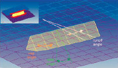 Altair HyperMesh pre-processing software includes connector technology that automatically assembles individual parts, modeling such structures as a seam weld. Image courtesy of Altair Engineering. | 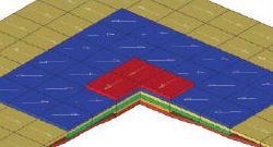 Altair HyperMesh is a high-performance finite element pre-processor that can prepare the largest models, even including composite structures, for analysis runs in different disciplines. Image courtesy of Altair Engineering. |
Altair Engineering s HyperWorks software includes HyperMesh, a powerful pre-processor first developed in 1990 and used extensively in automotive and aerospace applications. While readily handling simple models, it really shines when tackling detailed geometry or mesh in very large models. You can import geometry, other meshes and such information as ply thickness and orientation for working with composites. The software can automatically assemble and recognize spot welds, seam welds and bolted assemblies, and has full support for adhesive modeling.
Users can run HyperMesh in an auto-cleanup mode, where you define such criteria as what to do with holes smaller than a certain diameter. A batch mesher option is the most automated process, including geometry cleanup and meshing whose quality can be precisely measured; this is useful if you have, say, a full vehicle, that might consist of many hundreds of parts. You can submit them all at one time—and, by using multiple CPUs, get through a full vehicle quickly.
“Process automation doesn t mean you need to compromise on accuracy,” says Uli Gollwitzer, Altair Engineering marketing manager, modeling and visualization “You are able to set up all these control parameters, and you are still going to get the same level of quality.”
| A Quick Look at Meshing Options Editor s Note: Rick Matus, president of Pointwise (CFD meshing software), shared with Pam Waterman a quick pro/con comparison of meshing capabilities: If you are looking for a highly automated approach, maybe only requiring a single button-push to get results, then the CAD-embedded computational fluid dynamics/finite element analysis (CFD/FEA) solutions are the way to go. Engineers interested just in gross effects of the basic flow will probably be happy with CAD-embedded apps. The disadvantage is it does not always produce accurate results, and it is not always readily apparent when the results are wrong and by what degree. A standalone CFD/FEA package would typically provide more control over the mesh, solver and physical models. A CAD-embedded app might not include the model of a particular application, so you need to go to the standalone app to get the desired accuracy. Likewise, you may know a finer grid is required in a localized region in order to resolve a flow feature there. Highly automated meshers do not give you the ability to control the mesh to that degree, so this would be another case where the standalone CFD package would be needed. Sometimes even the standalone CFD/FEA apps do not provide enough mesh control, so you need a separate mesher to get the highest accuracy. |
Even the more specialized analysis packages can still target the engineer who is not a full-time analyst. To do so, Autodesk offers three choices in its Autodesk Simulation line, based on products acquired from Algor, Blue Ridge Numerics and Moldflow, as well as including some meshing inside Inventor Optimization.
Autodesk Product Marketing Manager Luke Mihelcic says customers need to spend time on efforts other than meshing, so the approach provides robust, fully automated steps inside their products that remove the guesswork. However, users can still choose to manually loosen, tighten or refine a mesh as desired.
Mihelcic notes that users get helpful visual results to make more adjustments.
“There are feedback tools that say, There are a lot of thin surfaces or thin edges in this model—you may want to consider adjusting your mesh in this location, ” he offers as an example. He adds that you can do mesh optimization studies within Autodesk Simulation CFD, telling it to run, for example, three or five mesh sensitivity studies, based on your direction to look at areas of high temperature or high pressure, etc. The software determines where there is or is not a lot of activity, and refines the mesh automatically.
The whole idea of evaluating meshing independently of the mathematical solvers invites discussion.
“Our view is that meshing is an integral part of the whole simulation process,” says Barry Christenson, ANSYS director of product marketing. “The more automated, the more integrated, the better. It also requires a high degree of synchronized development with your solvers. Maybe as you re developing new advancements in automation, you re developing new element formulations—to keep up with changes in element shape and uniformity. Your solver needs to utilize those meshes effectively.”
The capability to handle complex physics and their necessary meshes is reflected in COMSOL Multiphysics analysis software. It supports creating flexible, highly detailed versions, as well as importing third-party creations.
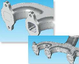
 Automatic tetrahedral mesh of the rear axle of a tractor, using ANSYS software. Image courtesy of ANSYS. | 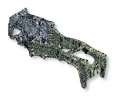 Automatic hex-dominant mesh of a clutch casing, using ANSYS software. Image courtesy of ANSYS. |
Comparing the two approaches, Lorant Olasz, COMSOL program manager of external interfaces, says the advantage of working solely within a certain package is that the software developers really know their users needs. Because the mesh may need to be constructed differently for each application, COMSOL Multiphysics offers tools that support optimizing the mesh for CFD, plasma, structural and many other analysis types. Physics-controlled meshing (with nine different preset mesh size settings) and user-controlled meshing each offer refinement options.
 COMSOL Multiphysics Cap Faces geometry operation is designed to make it easy to cover the ends of fluid channels and then mesh the interior of imported CAD parts. Image courtesy of COMSOL. |
 With PTC Creo Simulate, high-order, p-type finite elements follow the model geometry exactly. If part of the model is meshed with bricks for solution efficiency, the brick mesh is automatically transitioned and bonded to an unstructured tetrahedral mesh in the rest of the model. Image courtesy of PTC. |
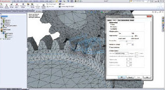 H-adaptive meshing control detail performed within SolidWorks simulation software. Image courtesy of SolidWorks. |
For users who rely on legacy systems or have in-house groups that do the meshing, Olasz suggests building a single mesh, then handing it off for designers to use in multiple analysis packages with structural or thermal specializations. With that in mind, COMSOL supports importing NASTRAN format meshes, and allows splitting a mesh into domains based on material data or element type.
Automatic adaptive remeshing is a hot topic, and it s one that figures prominently in SIMULIA s Abaqus/CAE software. The feature allows the program to work iteratively with Abaqus/Standard or Abaqus/Explicit to determine an optimal mesh—again demonstrating an advantage of working within a single environment.
For example, a sequential coupled thermal-structural analysis can progress from a coarse to fine mesh via a series of jobs submitted between the two programs. Each job communicates user-defined error-indicators that control remeshing iterations, balancing computational cost and accuracy. Such an optimized mesh would be difficult to generate manually.
The Abaqus documentation offers several recommendations about meshing decisions. The company even has a dedicated training class on selecting appropriate elements that help with special situations, such as bending or incompressible materials or a particular application.
“We ve found that most users learn very quickly what are the different element topologies and types to use,” says Asif Khan, Abaqus/CAE product manager.
Third-party Power
Pointwise CFD pre-processing software is joined by several other major, standalone packages that support detailed meshing capabilities. As mentioned earlier, Siemens PLM Femap is a well-known tool that people turn to when they are faced with challenging modeling or meshing problems.
“CAD-embedded FEA programs are great for creating push-button solid models from solid CAD data. However, you can very easily create huge models that become difficult or impossible to solve,” says Al Robertson, Seimens Femap marketing manager. “Femap provides a variety of capabilities to manage model size by idealizing the structure. It also supports more advanced analysis by creating specialized elements like nonlinear springs, rigid elements, spiders or mass elements.”
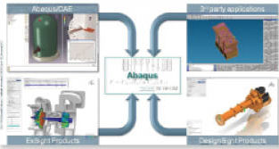 Workflow diagram for using SIMULIA s Abaqus/CAE multiphysics analysis software with optional third-party meshing functions. Image courtesy of SIMULIA. |
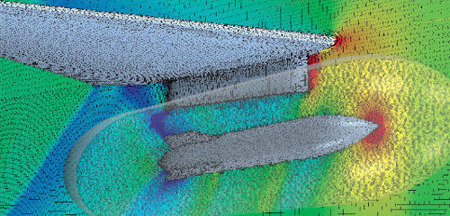
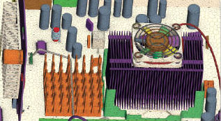 Mesh of an electronics-cooling layout for CFD analysis, performed with CD-adapco STAR-CCM+ software. Image courtesy of CD-adapco. |
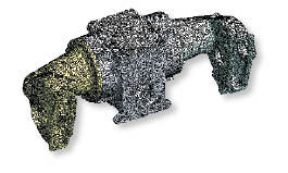
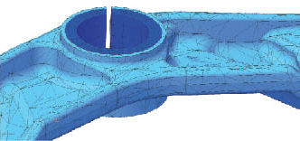
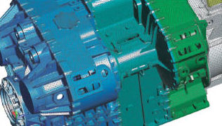 George Laird, principal mechanical engineer and owner, Predictive Engineering, says, “With the new automatic geometry preparation feature in Femap 10.3, our average speed for meshing a typical casting model is nearly 50 times faster. It s is a true game-changer in the world of meshing complex solid models.” Image courtesy of Siemens PLM. |
Robertson says the functionalities in the Femap Meshing Toolbox include tools to edit a mesh interactively once it s been created. It affords the user control over mesh sizing, seeding along edges, and even the ability to move individual nodes while conforming to the underlying geometry.
“In the just-released version, we re adding the ability to create surface geometry from existing shell models, modify or update the geometry, then remesh,” he adds. “This capability allows users to more easily make edits and updates to legacy finite element models for which there is no geometry available. “
For Robert Rainsberger, president of XYZ Scientific Applications, there are at least a dozen reasons to use TrueGrid, his company s specialized mesh generating software. He says many of the advantages stem from the fact that TrueGrid generates hexahedral element meshes instead of the automatic tetrahedral meshes commonly bundled with CAD systems or simulation codes. His top four include:
1. There is no need to clean up the geometry, because TrueGrid can handle gaps and overlaps.
2. The software can handle complex geometry, with no limit on mesh size. Rainsberger says a 1 billion-node TrueGrid mesh is unusual, but not uncommon.
3. TrueGrid is not restricted to common surface types.
4. Any aspect of the model can be parameterized, letting users try a variations either manually or via an automated search.
The rest of Rainsberger s Top 12 TrueGrid benefits address such features as being able to form boundary layers with high aspect ratios (typical for CFD analysis), dealing with anisotropic materials such as fiber composites, and accurately modeling elastic-plastic material models. He says it pays to use a versatile mesh generator to ensure success, flexibility and desired accuracy every time.
With all these choices, it s a good thing that the company websites offer detailed comparative charts and user webinars. Gather up your models; it s time to go for a meshing test drive. DE
Contributing Editor Pamela Waterman, DE s simulation expert, is an electrical engineer and technical writer based in Arizona. Contact her via [email protected].
MORE INFO
Subscribe to our FREE magazine, FREE email newsletters or both!
About the Author
Pamela Waterman worked as Digital Engineering’s contributing editor for two decades. Contact her via .(JavaScript must be enabled to view this email address).
Follow DE

