Fig. 1: The geometry model of the chassis.


Latest News
November 1, 2017
Editor’s Note: Tony Abbey develops and teaches both live and online FEA classes. He also provides FEA mentoring and consultancy. Contact [email protected] for details.
Many of you will have been faced with a situation where a design is changing rapidly and finite element analysis (FEA) simulation is struggling to keep up. Changes in geometry have a knock-on effect on the mesh, loads and boundary condition strategy. In this scenario, it is difficult to keep FEA in a proactive role in providing design direction, rather than being used in a reactive checking mode. This article reviews some ways in which FEA modeling can anticipate design changes and keep ahead of the curve.
Synchronizing FEA and CAD Models
If CAD geometry and an FEA model are linked together, then it may be possible to update the mesh, loads and boundary conditions automatically as geometry is changed.
The methodology will depend on whether the CAD geometry is driving the FEA model development or whether the FEA is working independently on imported geometry. CAD-embedded products are strongly oriented toward the former. FEA entities do not exist outside of the framework of the geometry. All FEA manipulation will flow down from geometry. The geometry can be manipulated to suit the FEA requirements, but this will be a development of the geometry parallel to the main design intent.
Traditionally, independent FEA preprocessor tools create a limited subset of geometry, but the geometry tools are at least a generation behind current CAD technologies. There is a much heavier emphasis on using the mesh to define geometric definition of the component directly.
This clear demarcation has been blurred over the past few years with new tools such as MSC Apex from MSC Software and ANSYS Workbench linked to SpaceClaim. These types of products move the design re-analysis process away from a CAD-centric to a more FEA-centric perspective, with more powerful independent geometry manipulation tools linked to meshing.
A CAD-centric Perspective
Looking first from a CAD-centric perspective, if the geometry changes are variations on a theme, then the updating can be relatively straightforward. For example, if the controlling dimensions change, but the overall topology stays constant, then surface definitions will be persistent. Most meshing, load and boundary condition definitions will be relative to surface geometry. If the surfaces are maintained, then the relationship to the FEA entities can also be maintained.
If the geometry is updated and features are modified, then the relationship of the surfaces will change. There is a good chance that the original surface definitions will be destroyed or distorted so that they are no longer applicable. This means that the task of applying loads and boundary conditions will have to be repeated.
It is always tempting to use only automatic global mesh size and other global mesh controls. It is usually very cost effective to overlay local controls over this. But this takes some dedicated effort and requires going up the learning curve. If the local controls will be disrupted every time there is a significant change, then this becomes an unattractive option.
Keeping comparisons of evolving geometry and FEA responses can be very useful. However, at some point the decision may be made to abandon this approach and instead consider the model to be a fresh configuration. This implies rethinking the FEA strategy from scratch. Broad metrics such as maximum stress and deflections are more useful comparators across significantly different designs.
An FEA-centric Perspective
With a more traditional FEA preprocessor, there is naturally a lot more control of the idealization as the design changes. The primary objective of these tools is to produce a mesh, and there are many, varied ways of achieving that. The challenge with these tools is to make them attractive to the design community, people who may not be thinking in terms of abstraction of FEA entities. As I have mentioned, there are new tools that focus on linking underlying geometry in a more powerful way to the evolving FEA model. These tools may be more attractive to the designer or part-time FEA user. The traditional dedicated FEA preprocessor uses geometry manipulation tools, which are unattractive to the designer.
The Dilemma
So, given a redesign, the big question is who will carry out the re-analysis? Is it more efficient to do this within a CAD embedded environment, or divert the task to an analysis-focused environment? The answer will depend much on the nature of the design and analysis process. I have talked to hundreds of clients about these issues. Their evolved solutions tend to have either FEA- or CAD-centric bias, but there are enormous variations within these central themes.
Using Modeling Idealizations
My background is FEA-centric, so I am familiar with driving design changes by rebuilding the FEA model. Years ago, FEA workflow originated with direct meshing with no underlying geometry. Later, 3D geometry techniques evolved ahead of CAD modelers, but they have never matured. Hence, their unattractiveness. However, dedicated preprocessors are intimately linked to the powerful concepts of idealization. Rather than modeling everything in 3D elements, there is an emphasis, where appropriate, on 2D shell and 1D beam elements. (Editor’s note: See page 13 for more on “dumb elements.”)
If using thin shell elements, a thickness variation can be achieved with one dialog box change. Similarly, beam cross-sections and their distribution can be updated rapidly.
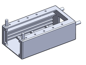
An example of the rapid reconfiguration that can be created is shown in Fig. 1. A main chassis supports printed circuit boards and heavier trays with electromagnetic equipment. Only the main chassis is shown in Fig. 1.
 Fig. 1: The geometry model of the chassis.
The equipment had to survive a harsh vibration environment, which required normal modes, frequency response, shock spectra and random response analysis.
It was important to start scoping the dynamic response of the design to ensure the structure was in the right ballpark for meeting the loading environment. For example, if resonant frequencies strayed into critical frequency ranges of the shock spectra or the random response specification, then they would need to be redesigned.
The design was still evolving, primarily from the perspective of the electronic equipment and its distribution throughout the rack. The dimensions of the rack were also subject to variation. A full assembly had been schemed and the part count was around 300. Of this, only around 20 were structural parts or had significant mass.
The electronic components were smeared over the structure using nonstructural mass. The heavier components were assumed to be very stiff. A combination of rigid spider elements and lumped mass elements were used.
Fig. 2 shows the solid element model of the main chassis. This had just under 1 million degrees of freedom. All of the structural components were modeled in a similar way and assembled using fully bonded contact. Total degree of freedom count was around 10 million. Normal modes analysis was fairly straightforward, but the dynamic response analyses became very tedious to run and check out, primarily because of the size of the model and the number of local modes.
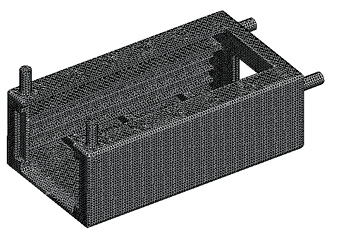 Fig. 2: The 3D element model of the chassis.
At this point, the design started to change almost every day. To be responsive I changed tack to a 2D and 1D model. This is shown in Fig. 3. In this case I set up the walls of the tray to have a regular mesh. This formed the pattern for any variation that would be required. The change in height of the trays or PCBs just meant a change in height of that particular mesh. I also used a simple subset of the surfaces extracted from the CAD geometry to allow easy manipulation. Mass and center of gravity of components could be rapidly adjusted.
In retrospect, bonded contact could have been used more extensively to avoid the need for conforming meshes. Edge-to-surface bonded contact is now much more robust and opens up even more possibilities for fast meshing.
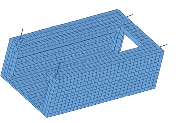 Fig. 3: 2D and 1D idealization of the chassis.
The initial analyses showed some worrying resonant frequency implications, particularly for the poorly supported printed circuit boards. One of the stiffer trays had a similar problem, due to the large components mounted on this. I was able to work rapidly with the designers to come up with stiffening schemes and mass redistribution schemes to alleviate the response to the shock and random response loadings.
At that point it was very tempting to start to work up the mesh into a better representation of the structure. However, this design was not frozen yet, and I wanted to wait until there was a definite decision to commit the configuration to the prime contractor. Indeed, at this point there were several significant configuration changes due to the electronic performance of equipment rather than the structural response. So, several more rapid evolutions of the resultant changes dynamic response were required. Compromises on structural response and electronic design expediency had to be carried out.
I do not have enough experience or skill working directly with CAD to be able to evaluate how quickly the changes could be affected in a full FEA/CAD embedded solution. I think the future holds a lot of potential, where the fidelity of the FEA tools and the subtlety of the CAD manipulation will be available within one program. With cross-training of analysts in a friendlier CAD tool and designers into a friendlier FEA tool, rapid and efficient working techniques will no doubt be evolving. I would also imagine that there would be many unique workflows developed, dependent on the particular talents of the engineers involved.
It is interesting to note the current emphasis on FEA democratization, putting FEA into the hands of the designer. I would also like to see CAD democratization, making CAD tools easy for analysts such as me to use!
More Info
Subscribe to our FREE magazine, FREE email newsletters or both!
Latest News
About the Author
Tony Abbey is a consultant analyst with his own company, FETraining. He also works as training manager for NAFEMS, responsible for developing and implementing training classes, including e-learning classes. Send e-mail about this article to [email protected].
Follow DE

