

Latest News
November 1, 2011
By Mark Clarkson
At first glance, fuel cells aren’t very complicated. Hydrogen gas (H2) is fed in under pressure through the anode to a catalyst, usually platinum, which splits it into positively charged hydrogen ions and free electrons. The anode conducts the electrons to an outside circuit to power a motor, etc., before they return to the cathode side of the fuel cell.
On the cathode side, oxygen (O2) gas is fed under pressure to the catalyst, where the molecules are split into negatively charged oxygen atoms. These combine with the returning free electrons and positively charged hydrogen ions—drawn from the other half of the cell through a one-way membrane—to form water (H2O.)
While the chemical reaction behind a fuel cell is simplicity itself, modeling one at any significant level of detail is a challenge. The anode and cathode use intricate channels to deliver their respective gases to the catalyst. The catalyst itself is a porous, composite material with an extremely convoluted or “rough” surface, to maximize the exposed surface area. To achieve reasonable voltages, multiple fuel cells are stacked together, connected with bipolar plates.
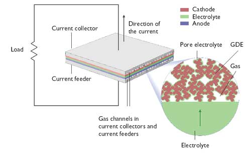
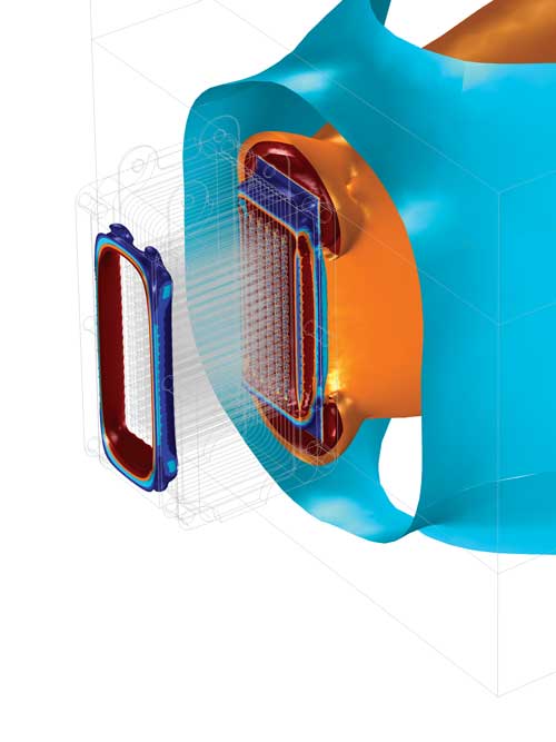
A unit cell in a fuel cell (anode, cathode, electrolyte and current collectors and feeders).
The image shows that the gas channels impede the transfer of current, while the parts
of the current collector/feeder that are in electronic contact with the electrode impede
the transport of gas to the electrode (optimization problem in design). GDE = gas
diffusion electrode. Image courtesy of COMSOL.
Any little bit can be surprisingly complicated to simulate. Take the basic matter of electrode thickness, for example.
“You have a tradeoff among conductivity, mass transport and current density distribution,” explains Ed Fontes, CTO of COMSOL. “If you make a thick electrode, you get a more uniform current density distribution, so the bipolar plate design is less critical. On the other hand, you get more ohmic losses and losses in mass transport. It’s a highly non-linear problem to optimize the thickness of the electrode depending on the operating conditions, catalysts and optimal properties. Even 1D models can be quite complex.”
Fully-coupled, Multi-scaled
What do you want to simulate? Are you doing transient analysis simulation to test various hypotheses about what’s causing your real-world test results? Are you concerned with the smoothness of the gas flow? Are you modeling the electric current? Heat transfer?
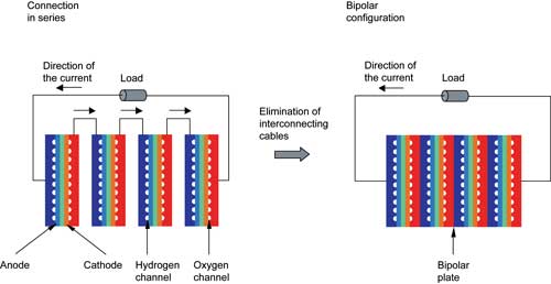
The electrical connection principle behind a fuel cell stack. Image courtesy of COMSOL.
There is, as they say, an app for that: computational fluid dynamics (CFD), system modeling software, and so forth.
That’s good, because a fuel cell design must balance the momentum of the fluids as they flow through the system, the energy transfer (heat, etc.); the transport of the chemical species (hydrogen, oxygen, water, electrons, etc.), and the electrical currents. That’s hard enough, but these are all closely coupled.
“When you consume oxygen,” says Fontes, “you’re transferring electric current, so the electric current balances are coupled with mass transport and fluid flow. The losses in the system produce heat, so you have heat transfer.”
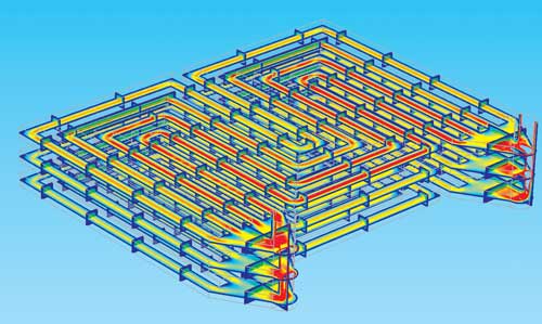
Flow field in the cathode gas channels in a set of three bipolar plates.
The performance of the electrodes and catalyst depends on the water content, so you’ll need to take evaporation and condensation into account as well.
Simulating all this is doable on an engineering workstation with software such as COMSOL, but only a bit at a time. The cutting edge is to model it all simultaneously and fully coupled.
“To run just CFD isn’t very interesting,” says Fontes, “so you try to couple CFD and fluid flow with heat transfer, with chemical species transport, and with electrochemical processes ]such as] electric and ionic currents.”
Not only do you want to have different coupled phenomena, Fontes adds, “you also want to have different scales—micro scale and macro scale. This is multi-scale modeling. That’s the absolute cutting edge in this field. You can move all the way to molecular simulations for the catalyst. There are national labs doing that.”
You won’t be doing this on your desktop anytime soon. On the other hand, simulations you can run on your desktop today took a supercomputer just a decade or so ago.
Coming of Age
“At Ford, we rely heavily on modeling,” says Dr. Dawn Bernardi, Ford research engineer. “Models are an integral part of ]fuel cell and battery] development.”
It wasn’t always thus, she says.
“We didn’t get respect in the old days,” says Bernardi. “People thought we were just ‘fitting things in.’ They’d say, ‘You could fit an elephant with a 200-term polynomial!’ They didn’t realize that our equations were based on true phenomena, like diffusion and reaction and heat transfer. They actually did mean something about the system.”
Today, she says, people are finally warming up to the concept because the models actually do work.
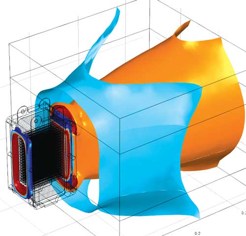
Flow velocity iso-surfaces of cooling air obtained from a CFD simulation of an
air-cooled stack. Image courtesy Siegel Schleimer Ing ©nieurs-conseils, Luxembourg.
“We’re able to rely on these models, because they reproduce all our life test results,” Bernardi says. “Now we can do a year’s worth of experiments, and then extrapolate out to 10 to 15 years of life. The challenge is simulating the degradative performance. Although our batteries are designed to outlive the vehicle, we still need to watch them reach their end of useful life.”
Fuel cells don’t last forever. They suffer corrosion, thermal cracking and other structure changes, not to mention abuse and accidents. Watching them age and die on computer is scientific research now, but the kind of simulation you can run on your workstation today was scientific research 10 or 15 years ago.
In another five to 10 years, this kind of information will be available in materials databases—just like the ones that inform today’s software about electrical conductivity and tensile strength.
Different aspects of the flow velocity field (from the ambient into the cooling channels
in the fuel cell stack).
The problem with fuel cells is that they’ve been the “next big thing” for, well, decades. Are they ever going to actually break through?
“I got this question during my defense of my PhD ]in 1995],” says Fontes. “I said, ‘This particular one I’m looking at, the expectations are too high. It’s never going to be as useable as people think.’”
That doesn’t really matter though, he says. The same methods and software apply to any type of fuel cell, to batteries, to solar cells, and even to corrosion.
Mathematical Battery Models Dr. John McPhee of the University of Waterloo heads a research team sponsored by Toyota and Maplesoft to develop models of hybrid electric vehicles and sub-systems. Their work is on batteries rather than fuel cells, but still uses simulations of physics and chemistry to aid engineers. Models developed by McPhee’s team are math-based, rather than numeric. “With simulations based on finite elements or finite differences or CFD,” says McPhee, “the math is embedded in the code. You can’t see the equations; all you see are nice animations or plots or reams of data.” That’s exactly what Toyota didn’t want, he says. “We created a pretty good circuit-based model of a battery,” he recalls. “It matched experiments and wasn’t too computationally intensive. The Toyota guys looked at it and said, ‘Where’s the chemistry?’ So we went back to the drawing board. We now model the actual chemical kinetics, and the rate of chemical reactions within different battery chemistries.” McPhee is quick to point out that you don’t have to know the math to work with the models. “The whole point of this three-way collaboration is for us to develop tools for MapleSim that Toyota can then use. We can’t overwhelm the front line engineers with equations. “An engineer can simply click-and-drag a NiMH battery into an electric vehicle simulation. They don’t have to look at the math, unless they want to. The difference is that in MapleSim, you can.” |
Contributing Editor Mark Clarkson is DE’s expert in visualization, computer animation, and graphics. His newest book is “Photoshop Elements by Example.” Visit him on the web at markclarkson.com or send e-mail about this article to [email protected].
Subscribe to our FREE magazine, FREE email newsletters or both!
Latest News
About the Author
Mark ClarksonContributing Editor Mark Clarkson is Digital Engineering’s expert in visualization, computer animation, and graphics. His newest book is Photoshop Elements by Example. Visit him on the web at MarkClarkson.com or send e-mail about this article to [email protected].
Follow DE

