

February 1, 2013
With system-level modeling, all the system components are simulated together in one environment. Complex and often competing requirements (such as engine performance vs. emissions, thermal battery requirements vs. energy used by the cooling system) and constraints (such as manufacturing cost and government regulations) need to be reconciled. System-level modeling makes it possible to optimize the overall design from the early stages of product development. This way, requirements are met, development timelines and costs are reduced, and products can be brought to market quickly in a competitive environment.
Modelica seems to be emerging as the standard for describing system-level models. Already pervasive in parts of Europe, we are seeing increasing penetration in other parts of the world, notably Japan and North America. A strong ecosystem is developing around the Modelica standard:
- Multiple tool vendors are providing software to aid in the construction of Modelica models.
- Library vendors are offering both free and commercial component libraries, extending the reach of the set of components that are part of the standard library.
- Consulting and training is readily available.
At its base, Modelica is a modeling language, supported by a standard library of components that cover many engineering domains like electrical, mechanical, thermal and fluids. Both the language and the standard library are developed and maintained under the auspices of the Modelica Association.
The most common way of interacting with Modelica is to use a tool to graphically build a model by selecting, connecting and configuring individual components taken from a library.
Fig. 1 shows a diagram for a double spring-mass-damper system, such as you would find in a suspension model. From left to right, we see a step input signal, connected to a force driver, followed by two sets of sliding masses connected to spring-damper components. Finally, the last spring-damper is connected to a fixed reference frame.
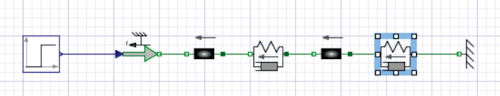 Figure. 1: Modelica diagram for a double spring mass damper system. |
Each individual component contains the dynamic equations that describe its behavior. Fig. 2 shows the governing equations that are encoded into the sliding mass component.
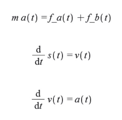 Figure. 2: Sliding mass equations. |
The variables s(t), v(t) and a(t) represent displacement, velocity and acceleration of the component, and m denotes its mass. The variables f_a(t) and f_b(t) are the forces acting to the left and right of the mass, respectively.
It is important to note that the equations, and thus the component, make no assumptions on how it will be connected to surrounding components. In particular, there is no assumption on what directions the forces on either end of the mass will take. This is at the core of why Modelica is referred to as an acausal modeling language, as opposed to causal systems, where the direction of flow has to be modeled explicitly.
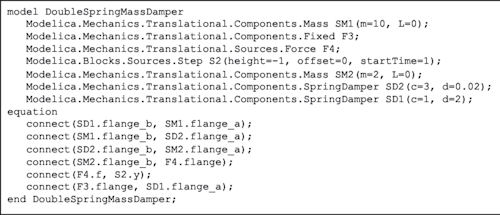 Figure. 3: Modelica code for double spring mass damper system. |
There are some advantage of acausal modeling: Subsystems can be more easily reused in different contexts, and model diagrams are typically much less complex, require fewer components and are easier to understand and modify because they more closely resemble the physical system being modeled.
The Modelica language has the capability to model using both causal and acausal paradigms—and indeed, mix the two in the same system model.
Looking back to Fig. 2, tools like MapleSim, Maplesoft’s system-level modeling tool, allow you to extract such equations from any component or an entire subsystem, enabling symbolic analysis that is not possible with just black box component models. However, the graphical diagram fully abstracts all of the underlying mathematics—and diving into the equation level is completely optional if you are just looking for simulation results. In that case, the tool will automatically generate the entire set of equations for the system diagram (in general, these will be systems of hybrid differential algebraic equations) by combining the equations from each component together with equations derived from the connections between the components.
For example, a mechanical connection between one end of the sliding mass and a spring damper implies that the displacement of the connected extremities is identical, and that the forces applied cancel each other. The entire system of equations is then simplified symbolically, and C code is generated that will be compiled and executed within a differential equation solver to provide simulation results.
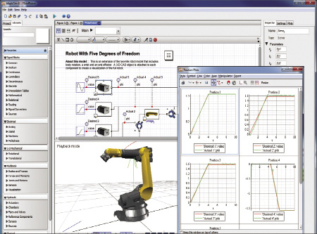 Figure. 4: Simulation results. |
The symbolic simplification step is a crucial part of this process. Not only does this involve transforming the set of equations into a solvable set; it also reduces the size of the equations and uses optimization techniques to yield efficient simulation code, without loss of model fidelity. This code can be executed within the Modelica tool environment, or exported to other parts of the toolchain. Simulation results are available as data tables, plots or three-dimensional visualizations (see Fig. 4).
Learning the Language
As easy as it is to interact with Modelica models at the graphical diagram level to get simulation results and perform analysis, drilling down to the language level provides access to the entire power of the Modelica modeling paradigm. Fig. 3 shows the Modelica code that underlies the system diagram from Fig. 1.
Within this code, declarations like Modelica.Blocks.Sources.Step refer to components within the Modelica Standard Library. The “connect statements within the equation section describe how these components are to be interconnected. Typically, the Modelica code also includes annotations that specify the graphical presentation of the model diagram, including location and size of the components as well as routing of the connections, but we have omitted these annotations for space reasons.
Because both language and base library are standardized, Modelica models and component libraries are portable among different tools, preventing lock-in to a particular vendor.
That bring us to the real promise of the Modelica standard for engineering companies around the globe: to be part of a growing ecosystem of vendors and consultants, where engineering models can be easily shared and are never tied to a particular tool or vendor, and to leverage an increasing body of knowledge in the form of component libraries and engineering expertise to bring better products to market faster.
Laurent Bernardin is vice president, research and development, for Maplesoft. Send e-mail about this article to [email protected].
INFO
Subscribe to our FREE magazine, FREE email newsletters or both!
About the Author
DE’s editors contribute news and new product announcements to Digital Engineering.
Press releases may be sent to them via [email protected].


