Motion Simulation Software Tools Part 1: The Computer Aided Engineering Spectrum, 2 in a Series
Crank it, slide it, rotate it -- how well will it do the job? A selection of computer aided design motion-simulation software helps answer the question.


Latest News
February 2, 2009
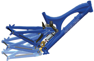 This overlay of three images of a Santa Cruz V10 bike suspension illustrates a significant amount of rear travel. The composite demonstrates the need to understand the complete range of space occupied by the motion event. Image courtesy PTC |
Your latest product design may exhibit pure mechanical genius or all the capabilities of a paperweight. How do you find out if your mechanism — an assembly with at least one moving part — is on the right track, from the simple question “Will the moving parts collide?” to “How well will it perform?” to “How long will it last?” Software that generates solid answers to these questions belongs in the realm of motion simulation.
A basic CAD system can do the job from purely geometric considerations; check out the free motion-simulation software from AR-CAD. And if you like to work with custom algorithms, consider the power behind The MathWorks’ SimMechanics. But if you need to look at the impact of different loads on the resulting range of motion, or predict mechanism durability, you probably need a finite element analysis (FEA). This article looks at the broad spectrum of motion-simulation packages, the tasks they can tackle, and the significance of their outputs.
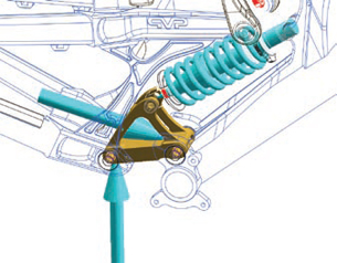 Once the kinematic and dynamic design is complete, the reaction forces (shown in blue) can be transferred for automatic inclusion in Pro/ENGINER Mechanica for structural analysis. Image courtesy PTC |
Kinematics Versus Dynamics
Many of today’s CAD design packages go well beyond the capabilities of even five years ago by looking at the kinematics of a mechanism — the motions of parts within a system without regard to mass or force. Kinematic analysis assumes all parts are rigid and translates all mated points and surfaces into various joints such as pin joints, ball joints, and sliders. Once the assembly is set in motion with a given speed, the software generates the resulting position, velocity, and acceleration of all connected parts. This approach does not provide insight into stresses or deformations, but allows you to evaluate and eliminate design paths that don’t meet basic operational requirements.
For example, in PTC’s Pro/ENGINEER software, you can literally drag on a part to view its path of motion. In addition, any time you build an assembly, the software builds a kinematic model, automatically defining the restraints based on joints and degrees of freedom (DOFs). But a kinematics point of view may not be enough. As John Buchowski, product manager at PTC, puts it, “With kinematics, you ask, given a certain speed, how will the other parts move? With dynamics, you tell it how fast and at what acceleration, then add mass. F=MA then allows you to extract forces.”
Pro/ENGINEER therefore performs dynamic analyses based on more realistic non-rigid parts, e.g., with a defined spring stiffness, so that you can identify the resulting force, transfer the loads, and see what stresses result. Buchowski adds, “We can do direct dynamics, where you apply a force and figure out how fast it will move, or indirect dynamics, where you tell how fast you want it to move and figure out what force or actuation it will take to do so.”
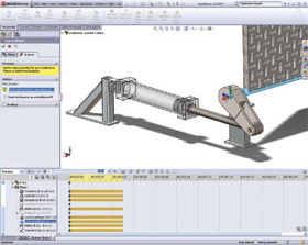
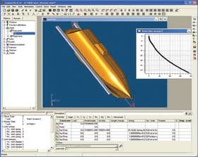
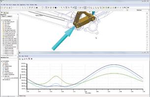 PTC Pro/E Mechanisms Dynamics showing graph and animated results for the mountain bike frame simulating the rear suspension absorbing 6 in. of travel. Image courtesy PTC |
Finally, by looking at coupled simulations that tie structural (FE) with dynamic analyses, you can tell if the moving parts will be strong enough for a given load. Buchowski notes that while you can do motion simulation starting directly with an FE model, it can be overkill in terms of both time and software resources.
SolidWorks’ family of software also offers a range of functions to move simulation further up front into design, not just in the FEA stage. As Kishore Boyalakuntla, SolidWorks’ Manager of Simulation Product Management, puts it, “When people do motion simulation, they want to make sure some assembly moves the way they want it to. For example, you use a garage door opener, the mechanism rotates, and the door lifts. You’re not really interested (at this point) in deflection or how much force it takes.”
SolidWorks offers users this type of kinematic analysis tool in its SolidWorks 3D CAD packages. Everything needed to perform motion simulation has been defined in the CAD assembly model and just needs to be transferred to the numerical solver. Assuming rigid bodies and few DOFs, the equations of motion are quickly solved. Results include displacements, velocities, accelerations, joint reactions, and inertial loads of all the components, as well as the power necessary to sustain the motion.
Boyalakuntla explains that for designers who want to move on to an FEA, the motion simulation outputs are exactly the inputs needed for structural analysis, which can be done in SolidWorks Premium. FEA capabilities are also available as a stand-alone add-in to other SolidWorks products. He adds that users can be sure of the best dynamic results if the values are automatically exported; likewise, if the user is working in an integrated environment such as SolidWorks, motion trajectories can be readily turned back into revised CAD geometry and used to define control system software.
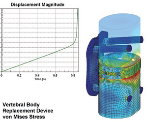 Saba Metallurgical and Plant Engineering Services used ALGOR MES to study this vertebral body replacement device. Analyses were run to determine the limit load based on allowable strain criteria and to determine the plastic collapse load.Image courtesy ALGOR |
Extending to Broader Analyses
ALGOR’s Bob Williams says motion simulation can be viewed as a progression because each method provides useful information under certain conditions. He points out, “Such technology is often included by default in CAD packages, allowing you to perform basic motion simulation to see how a linkage is going to move. Then, some packages have the ability to take output from the joints in those mechanisms.”
Using those loads as inputs applied to an FEA model, Williams says you can then run a static stress analysis and get a snapshot in time of the stresses on a given part in the mechanism. A step beyond that, then, involves using nonlinear analysisn to examine dynamic, rather than static, stresses. He says this approach, taken in ALGOR’s Mechanical Event Simulation (MES) software, can factor in nonlinear materials, contact forces, impact, and other complex situations.
Being able to do a full-blown FEA on a moving assembly can be critical. Williams explains, “There are a lot of assumptions about what the actual load is on mechanisms. In fact, determination of the loads is very complicated in many situations. For example, when simulating a drop test of a product such as a cell phone casing, dropping from just a few feet onto a hard surface can generate a significant load, and those forces can be changing throughout the entire analysis. With nonlinear FEA, instead of getting one snapshot in time, you’re potentially getting thousands of snapshots in time, with the forces changing, with the location of parts changing, and with the stiffness of parts changing as well.”
Acknowledging that a nonlinear simulation can be complex, ALGOR has focused on the user-interface aspect of MES software, making it comparable to setting up a static simulation, and including automated aspects to ensure convergence for faster solutions and accurate results as well as the ability to view results in real time.
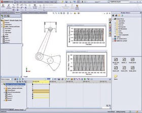
Motion simulation results from SolidWorks Motion provide data such as joint reactions and inertial forces; just the inputs needed for structural analysis that can be completed in SolidWorks Premium. FEA is also available as a standalone add-in to other products. Images courtesy SolidWorks |
Dennis Sieminski, director of marketing at NEi Software, echoes the thought that although you want an analysis to be close to reality, you are always making assumptions. He says, “You can do the kinematics ]rigid] analysis to determine velocities and accelerations, then get forces to use as inputs with an FE ]deformable] analysis. You need enough DOFs to accurately portray the model, but you also want it to mesh efficiently.”
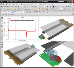 Motion simulation of a flat-bed scanner mechanism, evaluated with Siemens NX Motion Simulation. Image courtesy Siemens PLM Software |
NEi Motion addresses these tradeoffs using a dynamics solution from Fedem Technology. In order to simulate real-world dynamic events with long time histories, an automatic super-element method within NEi Motion reduces the number of DOFs to a minimum. A simulation can be made with an assembly containing both rigid and element models, and for rigid-body analysis, simulations are based on simpler geometry rather than elements.
Siemens PLM’s product family offers a full range of motion-simulation products from the kinematic capabilities within Velocity SolidEdge CAD software to the wide range of analysis capabilities in NX6. The company believes that the availability of a broad simulation portfolio within an environment saves an enormous amount of time because design changes can immediately update the motion simulation with no third-party interaction required. The integrated NX system also saves time by leveraging design conditions to define the joints in the motion analysis. Siemens is now extending the capability to include integrated motion control through a real-time analysis connection to Simulink.
Richard Bush, Siemens PLM Product Manager for Simulation, says that at the start of a project you should consider the best place to work and positively impact product performance. Modern design systems like NX provide a very scalable capability that supports complex problems in a dynamically changing environment; not just simple motion but perhaps with a control-loop system involved. He cites the customer application where a German automotive OEM designed a complicated 3-section roof mechanism, saying, “They used NX Motion Simulation to drive each joint by the hydraulic motor, and check for tolerance and positioning. If there was any change in the length of a part, then the motion would update. Mass properties also translated automatically. In a changing environment, that really pays off.”
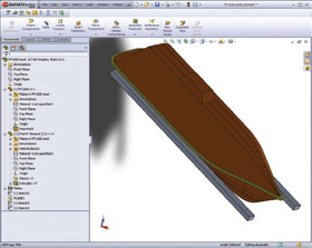
This NEi Motion analysis of a lifeboat for an offshore oil rig first examines the CAD model (left) as a rigid body to determine the velocities and angle of hitting the sea (dependent on drop height, launch-skid length, etc.). Results are then used for CFD analysis of boat/water impact. Images courtesy NEi Software |
Pay Now, Pay Later?
As ALGOR’s Williams says, “The design process is always a tradeoff: how much are you going to rely on experience from the past versus physical testing versus virtual testing?” As with all aspects of modern manufacturing, spending time and money earlier in the process to determine you’re on the best design path can save you major time and money down the road.
Stay tuned next month for more in-depth looks at the spectrum of motion simulation and analysis options.
| When Flexible Bodies help Richard Bush, Siemens PLM Software’s product manager for Simulation, explains that adding flexible bodies to a motion analysis is important when the assembly is subject to dynamic effects like sudden impacts or vibration. In addition, where there are multiple connection paths between the different parts of the assembly, flexible bodies enable correct joint forces and load paths to be identified. — PJW
|
More Info:
Pittsburgh, PA
Los Alamos, NM
Natick, MA
Westminster, CA
Waltham, MA
Plano, TX
Concord, MA
Subscribe to our FREE magazine, FREE email newsletters or both!
Latest News
About the Author
Pamela Waterman worked as Digital Engineering’s contributing editor for two decades. Contact her via .(JavaScript must be enabled to view this email address).
Follow DE

