

Latest News
December 4, 2001
By David Cohn
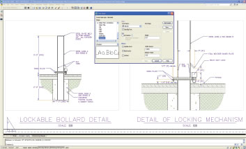 Figure 1:With annotation scaling, the same text, dimension, or hatch pattern appears at the proper size in multiple viewports regardless of scale, yet the location of annotative objects can vary between viewports. Any suitable object can be made annotative by simply activating its annotative property. |
How do they do it? After nearly 25 years, Autodesk still finds ways to improve its flagship CAD program. For each of the past four annual releases, Autodesk has surprised its customers with new features that really do make AutoCAD better and easier to use. In AutoCAD 2006, the major focus was on 2D drafting. In AutoCAD 2007, programmers turned their attention to 3D modeling and conceptual design. But for this, its 22nd release, the company has truly pulled a rabbit out of the proverbial hat — and customers are literally cheering when they witness the improvements in AutoCAD 2008.
Since its inception, one of the most difficult concepts for users has been the issue of scale. When you draw objects in AutoCAD, you typically draw full-size. If an object is two feet long, you draw it two feet long. Pretty straightforward, right? But when it comes time to add text, dimensions, cross-hatching, and callout symbols — basically any type of annotation that needs to remain a specific size regardless of the scale at which the drawing will be plotted — users had to decide in advance what size to draw those objects. For example, if you’re drawing something that will later be plotted at a scale of 1/8 in. = 1 ft.-0 in., you had to add text that was one foot high in order for the text to be 1/8-in. high when the drawing was printed.
If you later decided that the drawing should be printed at a scale of 1/4 in. = 1 ft.-0 in., all of the text you previously added had to be manually resized in order to keep its printed size 1/8-in. high. If a note needed to appear in two different views at different scales, you had to create the note twice, with all the attendant hardships if you needed to edit that note. And the same holds true for other annotation objects.
Some users solved this problem by creating many of their annotations in paper space, but this work-around was itself also problematic.
Annotation scaling Magic
With AutoCAD 2008, Autodesk has solved this long-time frustration with a new concept called annotation scaling. Any text, dimension, leader, hatch pattern, block, or attribute can now be defined as annotative, and any of these objects already present in existing drawings can easily be made annotative when that drawing is opened in AutoCAD 2008 by assigning it an annotative property. Any object with the new annotative property can then have one or more scales assigned to it, so that the same object can appear in different viewports with varying scale factors.
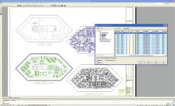 Figure 2: Users can now control appearance of layers on a per-viewport basis. Any layers whose settings are overridden in this fashion are clearly visible in the enhanced Layer Properties manager dialog box. |
When the scale of a viewport is changed, all of the annotative objects automatically resize based on the new scale of the viewport. For example, text defined to be 1/8-in. high remains 1/8-in. high regardless of the scale of the viewport.
Several new tools on AutoCAD’s status bar help users adjust the scale of any viewport. A new button makes it easy to lock or unlock a viewport and new drop-downs make it easy to change the scale of the viewport and to ensure that the annotative scale matches the scale of the viewport. In addition, when the same annotation is visible in multiple viewports with different scales, users can adjust the position of those annotations independently in each viewport. Yet any change to the annotation itself, such as editing the text, appears in each viewport — no more creating it twice.
Enhanced layer control
Another long-time user frustration has been the need to create extra layers just to control the appearance of objects. In the past, if you wanted an object to appear with a particular color or linetype in one view and a completely different color or linetype in another, you had to create the object twice, once on each layer.
AutoCAD 2008 adds new layer properties that can be specific to an individual paper space viewport, while the objects retain their original layer properties in model space. For example, users can select any viewport and then specify the color, linetype, lineweight, or plot style for any layers within that viewport. Now it’s easy to have fasteners appear dark on an assembly drawing and keep those same fasteners appearing grayed-out with wiring emphasized on an electrical drawing. This function also works with named layer states. Yet it’s just as easy to reset these properties to their original global settings if necessary.
Like Word and Excel
Many AutoCAD users create general notes in Microsoft Word and then cut and paste those notes into AutoCAD. But once in AutoCAD, those notes lose much of their formatting and appear as a single long column of text that shoots off the bottom of the drawing. It’s not surprising, therefore, that users have long wished that AutoCAD’s text commands worked like Word. Now they do.
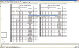 Figure 3: Text formatting is vastly improved and both multiline text and tables now support multiple columns. Table titles and headers can repeat in each column and AutoCAD tables support auto-fill similar to Excel. |
In AutoCAD 2008, when you insert text from Word, the text retains virtually all of its original formatting, including paragraph alignment, indentations, and spacing. In addition, multiline text now supports multiple columns. Text can automatically wrap across multiple columns and users can control the width and length of columns to achieve desired results.
This multicolumn capability can also be applied to tables. Users can now split tables into multiple columns and have table titles and headers repeat in each column. AutoCAD 2008 also supports auto-fill capabilities similar to those found in Excel.
And speaking of Excel, users have long wished for a method other than OLE (object linking and embedding) to truly link AutoCAD data with an Excel spreadsheet. The updated Paste Special command in AutoCAD 2008 lets users paste Excel data as AutoCAD table entities, creating a real data link between the DWG and XLS files. Should any data change in the XLS file, a bubble notification (similar to that for an external reference) immediately alerts you to the change and provides a quick way to update the table. You can also push changes in the other direction, so that if you modify data in the AutoCAD table, the data is also changed in Excel.
Spell checking has also been improved. Users no longer need to first select text objects; AutoCAD 2008 checks the entire drawing by default, and when an error is found, the software highlights and zooms to the misspelled word in the drawing. You can also include dimension text, attributes, and external references.
A new dimension
Leaders and dimensions represent another type of object that has long frustrated users. Leaders — the line and arrow that goes from a note or block to a specific area of a drawing — are often problematic. They were defined as a type of dimension and often did not appear as desired without a lot of additional editing, which often destroyed the link between the line and the note.
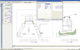 Figure 4: AutoCAD’s new leader capabilities let you add multiple leader lines from the same notation and align leader notes. Leaders are defined using a new leader style dialog box. Dimensioning is enhanced with automatic spacing and the ability to break dimension or extension lines where they intersect other objects. |
AutoCAD 2008 introduces a new object called a multileader. Not only can users now control the order of leader creation (head first, tail first, or notation first), but can also add multiple leader lines where needed. Multileaders are controlled by a new leader style, which lets users define the type of leader line (straight, spline, or none), type of arrowhead, leader connection information, and text information. It’s even simple to assign a block to a leader, useful for creating callout balloons. An associated new command lets you align multiple leaders while another new command collects multiple block-type leaders into a single multiple leader.
Even getting dimensions arranged, aligned, and oriented properly has also long been troublesome, requiring much manual editing. Here again, AutoCAD 2008 introduces several new commands. The new DIMBREAK command breaks dimension or extension lines where they intersect objects or other dimensions. The breaks automatically update if you move the intersecting objects, and heal themselves if objects no longer intersect. The new DIMSPACE command evenly spaces dimensions while the new DIMJOGLINE command lets users add a jog to linear dimensions.
Other enhancements in AutoCAD 2008 include the ability to control layers in DWF underlays, fade objects on locked layers, create multiline text attributes, and the ability to import and export MicroStation DGN files. In addition, the Dashboard, a user-interface component introduced in AutoCAD 2007, can now be customized using AutoCAD’s CUI environment, just like any other element of the user interface.
In previous releases, Autodesk boasted of hundreds of new features and functions. This time around, Autodesk hasn’t played up the number of improvements — one press release talks of “35 enhancements in response to customer visits, wish lists, and feedback forms.” But while AutoCAD 2008 may offer the fewest raw number of improvements of recent releases, the new features that have been added directly address long-held needs for thousands of users. And the ways in which they’ve been added make them easy to implement. Any existing text, dimension, or hatch pattern can be made annotative. The new layer functionality is a simple extension of AutoCAD’s existing Layer Properties Manager dialog box. And the annotative objects are backward-compatible with earlier versions of AutoCAD. Even the drawing file format remains the same as AutoCAD 2007, easing the transition to the new release.
AutoCAD 2008 is also the first release of the software to support both 32-bit and 64-bit operating systems, and AutoCAD 2008 can be run on Windows 2000, Windows XP, and Windows Vista.
It’s almost like magic. After 21 releases, Autodesk still manages to surprise us. And the well-designed and well-implemented new features may indeed make users conclude that AutoCAD 2008 is the best version of AutoCAD yet.
More Information
AutoCAD 2008
Autodesk, Inc.
San Rafael, CA
Price:
Full system: $3,995
Annual subscription: $450
Upgrade from AutoCAD 2007: $595
Upgrade from AutoCAD 2006: $1,195
Upgrade from AutoCAD 2005: $1,795
System Requirements
Operating System: Windows Vista, Windows XP Professional or Home (SP2), or Windows 2000 (SP4) (Windows XP Professional x64 Edition or Windows Vista 64-bit for 64-bit version)
CPU: Pentium 4, 2.2GHz (3.0GHz or greater recommended for conceptual design; AMD64 or Intel EM64T processor for 64-bit version)
Memory: 512MB RAM minimum (1GB for 64-bit, 2GB for conceptual design or 64-bit version)
Video: 1024x768 VGA with true color minimum (1280x1024 with 128MB video RAM and OpenGL or Direct3D recommended for conceptual design, Direct3D required for Windows Vista)
Other: Microsoft Internet Explorer 6.0 (SP1 or higher)
David Cohn is a computer consultant and technical writer based in Bellingham, WA, and has been benchmarking PCs since 1984. He’s a contributing editor to DE, an applications engineer with The PPI Group, and the author of more than a dozen books. Please send comments about this article to DE-Editorsmailto:[email protected]. You can also contact David at [email protected].
Subscribe to our FREE magazine, FREE email newsletters or both!
Latest News
About the Author
David Cohn is a consultant and technical writer based in Bellingham, WA, and has been benchmarking PCs since 1984. He is a Contributing Editor to Digital Engineering, the former senior content manager at 4D Technologies, and the author of more than a dozen books. Email at [email protected] or visit his website at www.dscohn.com.
Follow DE

