

Latest News
February 1, 2010
By Tom Kevan
This is the debut of a monthly column that will provide a fresh view of design engineering, one that takes into account the growing complexity of the machines and devices engineers are called on to create. It will mirror the increasing prominence of mechatronics, a design methodology that is a reflection of—and an adaptation to—changes that have transformed modern machines.
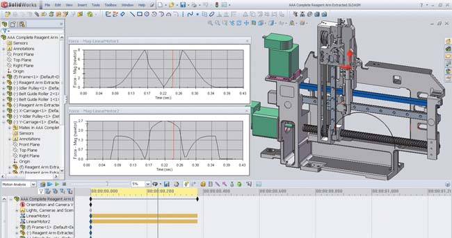 SolidWorks’ realistic machine simulations enable design teams to visualize the machine operating under the control of LabVIEW function blocks and obtain analysis data for optimization. |
Today’s machines have evolved from rigid, single-purpose devices—based on mechanical gears and cams—to flexible, multipurpose machines that incorporate sensors, actuators, embedded software, and servomotors. The metamorphosis is marked by a shift from purely mechanical devices to electromechanical collections of interconnected subsystems, whose functionality is defined by interdependencies that blur the boundaries separating mechanical, electrical, and software domains.
One of the primary difficulties encountered by engineers designing mechatronic systems revolves around the fact that optimal performance depends on complex interactions among the mechanical, electrical, and embedded control system components in the design. Until recently, your ability to model machines’ mechanical, electrical, and motion dynamics was limited. Mechatronic design tools that reduce the complexity of electromechanical system modeling just didn’t exist.
To fill this need, National Instruments and Dassault Systèmes SolidWorks Corp., have pooled their resources to create a Mechatronics Toolkit that combines the functionality of LabVIEW, SolidWorks, and COSMOSMotion. The toolset enables virtual machine prototyping and electromechanical simulation, all of which will help you develop complex multiaxis motion profiles for your machine and then validate them through simulation.
With the toolkit, you can design motion profiles, detect collisions, simulate the mechanical dynamics of a machine, estimate machine cycle-time performance, and validate motor, drive, and mechanical transmission selections. Another important feature is its ability to evaluate tradeoffs between mechanical, electrical, and embedded system aspects of your design, reducing risks and development costs.
Some typical applications for the Mechatronics Toolkit include motion trajectory design, visualization, collision detection, and motor, drive and transmission sizing.
For example, you can build motion profiles for operations composed of 2D straight-line, contour, and arc moves. The toolkit can handle 2D coordinated motion profiles and any number of uncoordinated motion axes. Each motion axis in LabVIEW will map to a constrained joint in COSMOSMotion and can then be applied as a displacement vs. time array.
In addition, using motion control profiles and timing/sequencing logic created in LabVIEW, you can animate a 3D SolidWorks model. Visualizing the operation of the prototype enables you to test the feasibility of your design. The integration of the toolkit’s software components allows you to transfer the visualization results from COSMOSMotion to SolidWorks Animator, and then convert the data to eDrawings, which can be shared with design team members, sales staff, and customers.
Using the collision detection functionality in COSMOSMotion, you can validate motion profile designs using a 3D CAD model. You can also check for interferences, evaluate the need for interlock control logic to prevent collisions, and test control system logic without the risk of damaging a physical prototype.
The toolkit will also help you calculate motor torque and velocity requirements for motion profiles. COSMOSMotion simulations factor in mechanical dynamic effects (e.g., payload mass, friction, and gravity), which helps you to make sound design tradeoffs when selecting coupled electrical and mechanical components.
It might be time to add to your mechatronics toolkit.Contributing Editor Tom Kevan is based in New Hampshire and is DE’s mechatronics, PLM, and systems expert. Send your comments about this article to [email protected].
Subscribe to our FREE magazine, FREE email newsletters or both!
Latest News
About the Author
DE’s editors contribute news and new product announcements to Digital Engineering.
Press releases may be sent to them via [email protected].


