

Latest News
June 1, 2008
By Rick Kuhlman
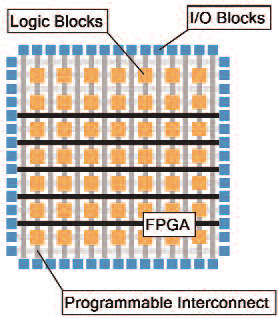 In this high-level view of an FPGA, the logic blocks are configured for processing tasks, the interconnect resources route the signals around the chip, and the I/O blocks drive digital pins to communicatewith the outside world |
The modern field-programmable gate array (FPGA), originally a prototyping platform for application-specific integrated circuits (ASICs), is now leveraged for many other applications due to decreasing costs and growing native functionality. Subsequently, use of FPGAs in a deployed embedded device is increasingly common but relatively new as a control system component.
FPGAs are useful in many control applications because of their inherent flexibility, performance, software reconfigurability, hardware reliability, and parallelism. Essentially, an FPGA offers a platform to create a custom digital circuit with both the performance benefits of custom hardware and time-to-market benefits of software definition.
Unlike a processor-based system, which uses serialized instructions and fixed register sizes, FPGAs are a matrix of configurable logic elements that can work independently and concurrently. This architecture can lead to a significant performance increase in control systems — often at a lower cost. In fact, Berkeley Design Technology Inc. (BDTI) recently benchmarked FPGA targets as consuming less power and being more cost-efficient per signal processing unit. All of these key benefits make FPGA a viable platform to use in a complex control system.
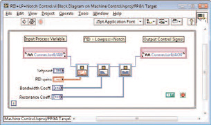 This fully synthesizable block diagram implemented in LabVIEW FPGA features an analog inputchannel, PID controller, notch and lowpass filter blocks, and an analog output. |
Further, as configurable parallel digital circuits, FPGAs are well-suited for many tasks in control systems. Pulse-width modulation (PWM) signal generation, for example, is perfect for FPGA implementation, especially because the timing accuracy and jitter implications of the duty cycle set point can significantly affect the performance of some control systems. Many designers also use the general-purpose digital signal processing (DSP) nature of FPGA to implement more difficult parts of the control system like a PID controller, notch filtering mechanical resonances, lowpass filtering of the input signal, or other pieces of complex control systems.
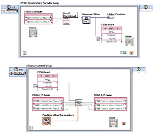 NI LabVIEWFPGA is a graphical programming language that integrates high-level function blocks, virtual wires for data flow, I/O interactions, and parallel processing, providing IP and a graphicaldevelopment environment that can be targeted to an FPGA. |
It has taken two decades for FPGAs to be used as a control system component for two primary reasons. The first is that software development tools are poorly suited for the control designer, having evolved through the expertise of the digital engineer (VHDL and other hardware description languages are different syntactically and conceptually from traditional control system design tools). The second is that adding FPGA implementations to system simulation models is difficult or impossible in many situations.
Intuitive FPGA Development Tools
To the first issue, higher levels of FPGA development abstraction must exist to narrow the gap between control designers and the hardware best suited for implementation. There are providers using C-to-gates technology to extract parallelism and generate hardware description language (HDL) from code written with a software mindset. Other vendors use a combination of sequential programming and configuration-based techniques to target FPGAs with software-like code and user-defined hardware optimizations.
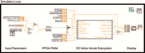 The LabVIEW Control Design and Simulation Module is a complete simulation package that allows users to insert LabVIEWFPGA implementations directly into the simulation loop. Furthermore, control designers can configure this code to be functionally and time accurate in a mix of discrete and continuous time solvers. In this figure, the FPGA PWM logic is placed in thesame simulation with DC motormodel. |
One intuitive approach to FPGA abstraction is graphical programming. Working in 2D space and “drawing” logic to form a dataflow diagram is an elegant way to represent an FPGA circuit. With this approach, control designers can easily see and implement parallelism — a key advantage of FPGA-based approaches over processors — by drawing their code in multiple parallel paths. Additionally, graphical languages have the advantage of representing the data flow through virtual wires rather than instructions. In VHDL (a common HDL), connecting two signals with a trace is an instruction that leads to a physical connection: data_a <= data_b. A graphical language uses a software “wire” to create a hardware connection. Intuitively representing parallelism and data flow is a key high-level feature that makes this type of abstraction uniquely suited for FPGA development.
For example, SpinX Technologies, a microfluidics device manufacturer in Geneva, Switzerland, used LabVIEW FPGA, a graphical programming tool, to implement a precise laser control system for use in a microfluidics test bed. Using LabVIEW, SpinX instantiated 13 control loops on a single FPGA chip to fully control laser positioning, firing, focusing, and feedback sensing.
FPGA in System-Level Simulation
As the adoption of FPGAs as deployment platforms for control systems grows, design and simulation tools must be able to simulate the coupled dynamics between the FPGA logic and multiphysics systems more tightly. Traditionally, HDL simulation tools provided information about the clock, digital bus, and signal-level timing performance of the FPGA logic. Unfortunately, it has often been labor-intensive, if not impossible, to validate system-level behavior across the multiphysics domain boundaries between FPGA hardware logic, software code running in a processor, analog-to-digital converters, signal conditioning circuitry, electric motors, hydraulic actuators, and mechanical assemblies.
Validating the design of such FPGA-based control systems requires a simulation environment that can span the domain boundaries to accurately model the coupled dynamic behavior of an electromechanical system. This approach to design enables the designer to simulate the FPGA in the context of the dynamical world in which it is used, as well as to examine the complex interplay between the FPGA logic inside the chip and the outer electromechanical world. The key is that FPGA code must simulate in a functionally correct and time-correct manner in a mixed continuous/discrete time simulation environment containing variable time-step solvers. Designers must be able to specify the discrete execution rate of the FPGA block and run the code in the simulation environment without skipping execution cycles. This is sometimes referred to as “cycle by cycle” or “cycle accurate” simulation.
Special Requirements
There are special requirements for simulation packages to incorporate FPGAs, including:
• Users must be able to simulate the function and timing of the code written for an FPGA inside a simulation diagram, essentially being able to run the same code across platforms in hardware and on a PC for simulation.
• Because FPGAs always depend on a hardware clock, the simulation environment must have a way to pass a simulated clock signal to the FPGA function block. This clock signal must be linked somehow to the overall simulation time clock.
• There are times when control designers need to create code that can adapt to the platform it is targeted to for simulation purposes. For example, the FPGA code may include hardware-only constructs of I/O, hardware FIFOs, pipelining, or a register that might not directly translate to a software simulation. With conditional compilation, users can isolate hardware-only aspects and compile simulation code alongside the FPGA logic for running simulation on a PC. When targeted to the actual chip, the code automatically changes to the functionally identical hardware implementation.
• Finally, many FPGA block execution times are based on digital events rather than on a fixed discrete-time step. Hence, the simulation environment must also have the ability to trigger execution based on events that occur at arbitrary times during the simulation. For variable step-size solvers, there needs to be a function to force the differential equation solver to evaluate and update the simulation output when a discrete event occurs.
FPGAs are growing in the control space, being used for general machine control, precise motion and laser control, hardware-in-the-loop applications, and other complex systems. Designers have achieved important performance gains, but they continue to need higher levels of abstraction and the ability to include FPGAs in system simulations. LabVIEW with the LabVIEW FPGA and LabVIEW Control Design and Simulation software modules is one way that vendors are turning this concept into reality.
More Information:
BDTI
Oakland, CA
National Instruments
Austin, TX
SpinX Technologies
Geneva, Switzerland
Rick Kuhlman is a product marketing manager for LabVIEW FPGA. You can send an e-mail about this article to [email protected].
Subscribe to our FREE magazine, FREE email newsletters or both!
Latest News
About the Author
DE’s editors contribute news and new product announcements to Digital Engineering.
Press releases may be sent to them via [email protected].


