

Latest News
July 30, 2007
By Al Dean
Like other similar vendors, SolidWorks, a stalwart in the industry for almost 14 years, has grown to the point where one begins to wonder exactly where the developers find room to squeeze in new functionality, new capabilities, and new innovation. In the case of SolidWorks specifically, though, the company is not content to simply rest on its laurels.
The new heads-up user interface allows the user to concentrate on the part and assembly, rather than finding menus, toolbars and such to define geometry. Features are dynamically edited, in real time, with fully dynamic previews of the end result of the modification, rather than showing the part in a rolled-back state.
When you start up SolidWorks 2008, the first thing that will hit you is the extensive overhaul of the user interface (UI). The new UI is in the style of Microsoft Office 2007, although not exactly the same. What you gain is a method of interaction that hides away much of the clutter that is inevitable in such systems, but makes the whole system very task specific. So, in the Command Manager you now have single toolbar stripes for Sketching, Features, Assemblies, Drawings, etc. The PropertyManager, through which you access the Feature Tree as well as operation parameters and inputs, is automatically hidden on the left of the screen.
Alongside this, there has been a rethinking of how you interact with data onscreen — this manifests itself in many areas, as we’ll discover, but in general terms, there is a lot more interaction directly with the model. This extends to presentation of options and commands at the cursor, rather than resorting to menus or toolbars. For example, toolbars pop up at the cursor as they do in Office 2007, and hitting the S key brings up a fully customizable and context-sensitive strip of commands.
The way in which you interact with much of the geometry has also changed, and much of this is collected under the SWIFT (SolidWorks Intelligent Feature Technology) banner, which has gotten much concentration in the 2008 release. You can now drag and drop many more features without having to roll back the feature history. What this means is that you can edit a part’s form instantly and immediately see the effects of that change, rather than waiting for a regeneration of the part.
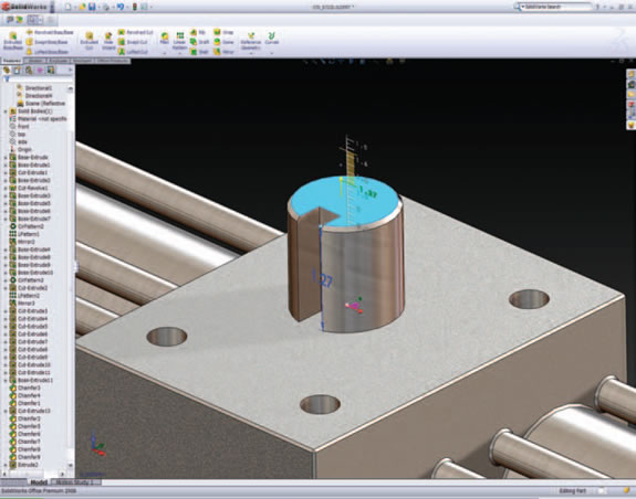
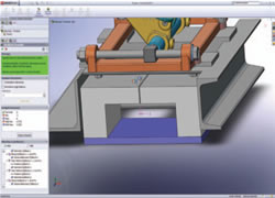
The new Live Section tool allows you to edit the cross-section of a part dynamically with full shaded previews, yet respects any pre-existing modelling and sketching constraints you have already defined.
Shifts in Geometry Manipulation
Features such as fillets, extrudes and such can all be selected, dragged, and dropped. There are several new tools to assist with the process, such as the new Rule that pops up, encapsulated in the Instant 3D concept. Rather than editing features explicitly, you can now interact with your 3D geometry in a much more freeform manner; features can be edited onscreen, with recourse to the PropertyManager, feature history, toolbars, or menus. Click the geometry associated with a feature, drag, drop, and edit — without feature history rollback and regeneration. Another good example is the workflow for creating sketch-based features. You create your sketch, exit it, then just click on the profile, and the system recognizes that you’re going to want to create an extruded feature and allows you to simply drag it out. Now, this only works with simple cases and single closed boundaries, but is intelligent enough to recognize whether you’re adding or removing material based on the geometry from which it’s built, and which direction you’re dragging.
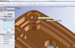
Another example of this shift in geometry manipulation is Live Section editing. This allows you to create a section through a part, then drag and drop geometry, without having to edit the underlying sketch. Of course, you’ll be wondering how that works with respect to constraints and parameters, and handily, the section entities are color-coded: magenta shows entities that can be moved, while non-editable entities are colored black.
 | 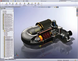 |
| At left, a model with the RealView effects switched off. At right is an image of the same model with the RealView option turned on.Materials are represented more accurately; real-time reflections are in place.This is ideal for visualizing how your product will appear and will prove invaluable for design review by removing much of the need to generate separate fully rendered images and animations. | |
While the Live Section and Instant3D functions are quite general and can be applied to almost any type of geometry modeling operation or process, there have also been other more specific operations that have been reworked. For example, in the 2007 release, the FilletXpert got the SWIFT concept applied to the creation of Fillet commands, where the system would automatically calculate the optimum grouping and construct order to achieve the results you want. This has been built upon to make both the automated assignment of fillets to the model and the corner treatments much more efficient with options that can be cut and pasted, adapted on the fly, rather than rebuilding the geometry.
Automating part documentation
Another perennial favorite of the 3D modeling software vendor is the whole concept of modeling in 3D and getting your drawings for free — but the stark reality is that this is rarely the case. The dimensions, constraints, and parameters you use to define your 3D models are very rarely the same dimensions you would use to define the form for manufacturing. This release gives a huge boost to the automated dimensioning tools added in the last few versions that enable you to quickly create the dimensions you need to manufacture a part from your 2D drawings. They are found in several areas, but most noticeably with (the wonderfully oxymoronically named) DimXpert.
This function takes the concept of automated dimensioning of drawing views and applies them to the 3D model. For example, there is a growing trend led by the automotive industry to fully document a 3D model, rather than just use it as a geometry storage medium, then reserve the drawing for capturing that vital manufacturing data. You set up standard tolerance conditions, preferences, and tolerance schemes (both plus-minus or geometric), add key data to your model, then let the system do the work. The result is a 3D model with the geometric dimensioning and tolerancing (GD&T) you need to manufacture that model, set out in various viewing planes as defined within the ASME Y14.41 standard.
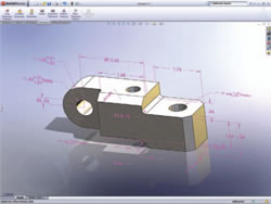 | 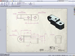 |
| DimXpert brings together a new set of tools that get you to a fully dimensioned part model in a fraction of the time — all of which conform to ASME Y14.41 standards for 3D documentation methods. | |
I’m not going to pretend that you’ll hit the go button and work with the results, as there is always going to be some form of modification — but the system can help you get a long way into the process automatically. Of course, once you have your dimensions and annotations in place, you then must ensure that it can be manufactured, which comes down to Tolerance definition.
TolAnalyst was initially shown at SolidWorks World 2006 and the sharper attendees will have noticed that it was shown again at this year’s event. The good news is that this is now part of the 2008 release and looks impressive. Essentially, TolAnalyst is automated tolerance stack-up functionality built directly into SolidWorks, which helps users “verify fit and function of designs.” It does this by looking at the order and manner in which parts are to be assembled and the geometric dimensions and tolerances you’ve already defined within DimXpert. This is critical for those working in a supplier-driven market, where many products are assembled from outsourced components — so the tolerances specified in your supplier’s datasheets can be incorporated in the tolerance stack-up.
TolAnalyst represents the manual process that many engineers go through to define those critical tolerances that can “make or break” parts during manufacture and allows you to find worst-case max/min, RSS max/min, and a contributor’s list by percent influence on tolerance. The whole process is driven by a wizard in the PropertyManager, and results are presented in real time. What this means is that your knowledge of your part performance, manufacturing requirements, and fit and function can be used to define tolerances, experiment with assignment and specific values, and directly and instantly see what effects those values have on the manufacturability of your part, which is better than trying to do it by hand and chasing 0.1mm around your parts to achieve the desired results.
 The new FilletXpert expands upon the SWIFT tools introduced in the last release to assist with automatically applying multiple fillets in a single operation. |
What’s important is that this information is then stored within the digital model and can be documented with ease and shared with your manufacturing partners.
Large Assembly Tools
In SolidWorks 2008, large assemblies get attention with regard to the opening and handling of large datasets and getting at the parts and subassemblies you want to work on. Using the new QuickView and Selective Open options, the system will load only the graphics of the assembly file, no part or feature information — and for SolidWorks users, this is even lighter than when using lightweight mode. It lets you select the parts you want to actually open, either by box select (which uses a very clever bounding box graphic method) or by individual selections. While you could manage this using configurations, you would also need to suppress parts and their associated mates. With the new method, those parts are hidden rather than suppressed and mates remain active, so while you might not have an entire mechanism loaded, you can still see how it would function using all of the constraints and relationships you’ve applied. Display States are not dynamic so they won’t dynamically update if you change things that fall within the search criteria.
Integrating Animation & Motion
Much work has been accomplished to consolidate certain SolidWorks functionality into a single cohesive environment for studying and presenting the motion of a product. While SolidWorks has had Animation tools and added motion simulation tools, these related functions were split across several modules and add-ins — some available to every user, some not. What the 2008 release does is consolidate this functionality into a single environment called MotionManager available to every SolidWorks user (although the CosmosMotion module is still only available in the higher-end bundles).
 The TolAnalyst tools allow you to conduct tolerance variance and stack-up analysis to ensure that the tolerances you define allow the part to be manufactured accurately enough to be suitable for its purpose, fit, and function. |
MotionManager starts with the basic animation tools. These are the key-frame animation tools many users are already familiar with. You set up how you want your parts to move, and the system interpolates between them to create animated sequences.
What’s interesting is that everything you do here can be used downstream. For example, when you create your mating conditions within your assembly, you are also creating the assembly constraints used in motion studies (previously you would pretty much have to redefine them from scratch); the same is true of physical motion drivers, damping constraints, and others. This will benefit your animations by making them much more realistic, but when you find yourself in a position to conduct motion simulation using CosmosMotion, that data is already defined, so you just hit the Motion and Kinematic Simulation toggle and run it, extracting the information you need.
A Systemic Shift
I’ve focused on a few of the real highlights from the SolidWorks 2008 release. What you have in this review are the new additions, features, and functions that I thought would be most applicable to the widest range of both existing and prospective users. When you look at a system like SolidWorks (and its competition), it’s important to realize that we’re now in a mature market where the majority of software can do the job. The challenge that most vendors now face is not geometry creation, but rather the efficiency of the tools, how they operate, and the downstream benefits you can derive from modeling and drawing creation. Ultimately, what this release represents for all concerned is a dramatic shift in how SolidWorks operates. The user interface work, when combined with the SWIFT technology, demonstrates a move toward a system in which you work with geometry, rather than against it.
The move away from explicit operation toward a more dynamic interaction is a growing trend — with one important goal. That goal is to allow you to design and engineer products, rather than operate a CAD system. When the barriers of learning a software tool are removed by making the process more intuitive, then you can concentrate on the task at hand, developing a product. What’s interesting is that now you can incorporate more manufacturing data to document a part more fully, both within its own singular context and for the parts with which it interacts when assembled. The DimXpert and TolAnalyst tools provide the key to this, so that you’re defining much more than geometry and real data about how a part is manufactured — backed up with the tools to verify, document, and disperse that critical information.
There are those who say 3D modeling technology is a staid and unexciting market, but when you look at SolidWorks 2008, you can’t help but think that a new era is coming. One where ease of use isn’t a factor; instead it’s one where you can use every bit of skill and knowledge you have on the deliverable product rather than the process of defining it in 3D.
SolidWorks 2008SolidWorks
Natick, MA
solidworks.com
Al Dean is technology editor at MCAD Magazine, a UK product development and manufacturing technology journal (mcadonline.com) and is editor of Prototype magazine (prototypemagazine.com). You can send comments about this article to DE-Editorsmailto:[email protected].
Subscribe to our FREE magazine, FREE email newsletters or both!
Latest News
About the Author
DE’s editors contribute news and new product announcements to Digital Engineering.
Press releases may be sent to them via [email protected].


